
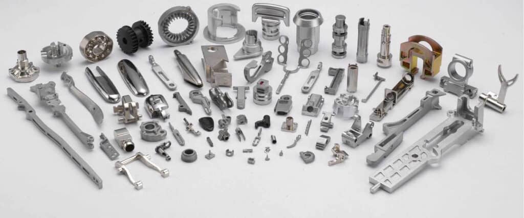
Micro MIM: Thin-Wall & Miniature Metal Injection Molding
Quick Answer: Micro MIM (μ-MIM) is the miniaturized branch of metal injection molding, built to produce metal parts measured in millimeters — often with micro-scale features and walls as thin as 0.1–0.3 mm. It uses finer powders, tighter tooling and closely controlled feedstock to hold tolerances around ±0.01–0.03 mm on critical dimensions, at production volumes where micro machining or stamping become uneconomical. Typical applications include medical and dental components, electronics connectors, micro gears and watch parts.
Standard MIM already handles small, complex parts well. But a growing share of demand — minimally invasive surgical tools, wearables, micro connectors, precision mechanisms — sits below the comfortable envelope of conventional MIM. Micro MIM pushes the same powder-plus-binder process into that territory, and this page covers what changes when parts shrink: capability limits, materials, design rules and quality control.
What Is Micro MIM?
Micro MIM follows the identical four-step route as conventional MIM — feedstock compounding, injection molding, debinding and sintering — but every step is pushed to a finer scale. Powders drop from the typical 2–20 µm range toward sub-micron and fine gas-atomized grades; mold cavities are machined with micro-EDM and micro-milling to reproduce features invisible to the naked eye; and shrinkage, still 15–20% during sintering, must be controlled to micron-level uniformity because even a small percentage variation is large relative to a 2 mm part.
The result is a process that produces millimeter-sized components with micron-sized features — parts that are often only fully visible under a microscope — in the same alloys and at the same high volumes that make conventional MIM attractive.
Micro MIM vs Conventional MIM
- Part size: conventional MIM typically covers 0.1–200 g parts; micro MIM works at the millimeter scale, with part weights measured in milligrams to fractions of a gram.
- Wall thickness: conventional MIM design rules call for roughly 0.5–6 mm walls (see our MIM size limitations guide); micro MIM routinely produces 0.1–0.3 mm walls, and research-grade μ-MIM has demonstrated walls near 50 µm.
- Feature resolution: micro MIM holds structural details in the low tens of microns — fine teeth, thin ribs, small bores and sharp edges that conventional tooling cannot fill or eject reliably.
- Tolerances: where conventional MIM quotes ±0.3–0.5% of dimension, micro MIM targets ±0.01–0.03 mm on critical features, with tighter results possible through secondary machining.
- Feedstock: micro MIM demands finer, cleaner powder with tighter particle-size distribution and exceptionally homogeneous mixing, because a single agglomerate can be as large as the feature being molded.
Design Capabilities and Limits
The practical envelope for production micro MIM:
- Minimum wall thickness: 0.1–0.3 mm depending on alloy, wall height and aspect ratio; thinner is possible in development but yield and distortion risk climb quickly.
- Part envelope: from sub-millimeter up to roughly 20 mm; beyond that, conventional MIM is usually the more stable route.
- Tolerances: ±0.01–0.03 mm on critical dimensions as-sintered; ±0.005 mm class features via secondary CNC or grinding — see MIM CNC secondary operations.
- Surface finish: fine powders sinter to smooth surfaces suitable for polishing, and sharp edges and high-aspect-ratio structures remain crisp after sintering.
- Density and properties: 95–99% of theoretical density, giving mechanical properties close to wrought material — essential for load-bearing micro components.
Materials for Micro MIM
Micro MIM runs the same alloy families as conventional MIM, selected from our MIM materials portfolio:
- Stainless steels (316L, 17-4 PH, 304): the default for medical, dental and wearable parts — corrosion resistant, polishable, and biocompatible grades are available.
- Titanium and Ti-6Al-4V: lightweight, biocompatible and strong, used for premium wearable housings and implant-adjacent components.
- Low-alloy and tool steels: for micro gears, pins and wear components that need hardness and fatigue strength at small scale.
- Specialty alloys (Co-Cr, Fe-Ni, tungsten alloys): for magnetic, wear-resistant or high-density micro parts; difficult-to-machine materials are where MIM's net-shape advantage is largest.
Where Micro MIM Excels: Applications
Micro MIM wins where three conditions coincide: the part is small, the geometry is complex, and the volume is high. Proven application areas include:
- Medical and dental: minimally invasive surgical instrument jaws, biopsy forceps, orthodontic brackets, endoscopy components — parts that must be small, strong and biocompatible. See our medical MIM capabilities.
- Electronics and connectors: micro connector housings, shielding parts, SIM/ejector mechanisms and sensor components for consumer electronics and wearables.
- Precision mechanics: micro gears, pinions, cams, levers and watch components such as cases, crowns and clasp parts.
- Fluidics and optics: micro nozzles, valve components and mounting structures where thin walls and fine bores define the function.
Design Guidelines for Thin-Wall and Micro Parts
The rules of our MIM design guide still apply, but micro parts tighten every tolerance on them:
- Keep walls as uniform as possible — at 0.1–0.3 mm thickness, a 2:1 thickness transition that conventional MIM tolerates becomes a distortion and cracking risk.
- Use generous radii; sharp internal corners concentrate stress and interrupt powder flow in thin sections.
- Position gates so flow fronts fill thin walls first and weld lines land on non-critical surfaces.
- Design for shrinkage anisotropy: on a 2 mm part, 16% shrinkage is only ~0.3 mm, but ±0.3% variation on that shrinkage is already 6 µm — a visible fraction of a micro tolerance band.
- Plan handling: milligram-scale green parts are fragile between molding and sintering, so part geometry and fixture design should minimize handling steps.
Quality Assurance for Micro MIM Parts
Conventional inspection tools hit their limits at micro scale, so micro MIM quality control leans on metrology built for small features: toolmaker's microscopes and vision systems for dimensional checks, micro-CT for internal porosity and wall-thickness verification without sectioning, and surface profilometry for finish-critical parts. Sintering runs use calibrated shrinkage factors per alloy lot, and statistical process control tracks critical dimensions across the cavity population. For medical programs, this metrology supports the supplier quality-system expectations described on our medical industry page.
Frequently Asked Questions About Micro MIM
Q: What is micro MIM?
Micro MIM (μ-MIM) is the miniaturized form of metal injection molding: fine metal powder and binder are injection molded, debound and sintered into millimeter-sized metal parts with micron-scale features. It uses the same process steps as conventional MIM, with finer powders, micro-machined tooling and tighter process control.
Q: How does micro MIM differ from conventional MIM?
Conventional MIM covers parts of roughly 0.1–200 g with 0.5–6 mm walls and ±0.3–0.5% tolerances. Micro MIM produces millimeter-sized parts weighing milligrams, with walls of 0.1–0.3 mm, feature details in the tens of microns, and tolerances around ±0.01–0.03 mm on critical dimensions.
Q: What is the minimum wall thickness in micro MIM?
Production micro MIM typically holds walls of 0.1–0.3 mm, depending on the alloy and the wall's height and aspect ratio. Research-scale μ-MIM has demonstrated walls near 50 µm, but at that level yield, distortion and handling risk rise sharply, so production designs stay in the 0.1–0.3 mm window.
Q: What tolerances can micro MIM achieve?
As-sintered micro MIM parts typically hold ±0.01–0.03 mm on critical dimensions. Tighter features — down to the ±0.005 mm class — are achieved with secondary CNC machining or grinding on the specific datums that need it.
Q: What materials can be processed with micro MIM?
The standard micro MIM materials are stainless steels (316L, 17-4 PH, 304), titanium and Ti-6Al-4V, low-alloy and tool steels, and specialty alloys such as Co-Cr and Fe-Ni. Because micro MIM forms the shape in the mold, it is especially economical for hard-to-machine alloys.
Q: What are typical micro MIM applications?
Typical applications are medical and dental components (surgical jaws, orthodontic brackets), electronics parts (micro connectors, shielding, sensor components), precision mechanics (micro gears, watch cases and clasp parts), and fluidic components such as micro nozzles and valves.
Q: Is micro MIM cost-effective for high-volume production?
Yes — that is its core advantage. Once tooling exists, micro MIM produces thousands to millions of small complex parts at a per-part cost far below micro machining, and with better feature resolution and material properties than stamping or die casting at that scale. It is most economical when the part is small, geometrically complex, and needed in high volume.
Source Micro MIM Parts from Emitech
Nanjing Emitech runs the full chain from in-house feedstock compounding through sintering, secondary machining and micro-metrology. Custom MIM parts · MIM services · Request a quote