
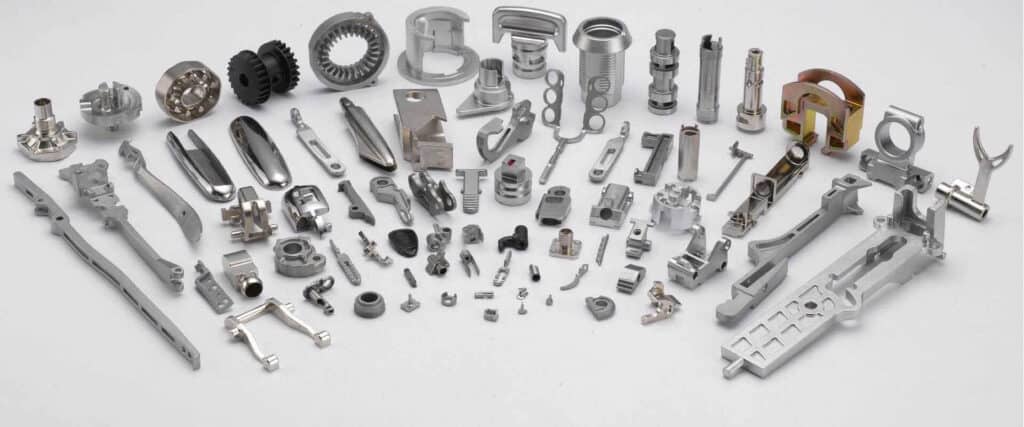
MIM Process Steps: Feedstock to Sintering
Quick Answer: The metal injection molding (MIM) process converts fine metal powder into dense, net-shape parts through five sequential steps: feedstock compounding, injection molding, debinding, sintering, and post-processing. The result is a complex metal component with 95–99% of wrought density and tolerances down to ±0.3%. At Emitech, we run the full MIM workflow in Nanjing, from tooling design and feedstock qualification to final inspection and surface finishing. Our MIM production capabilities page documents the machines, tolerance tables, and capacity behind that workflow. This guide explains each step with practical parameters.
Metal injection molding bridges the design freedom of plastic injection molding with the mechanical performance of engineered metals. For buyers evaluating MIM against machining, casting, or powder metallurgy, understanding the exact MIM process steps is the fastest way to judge feasibility, cost, and lead time. Below is a practical walkthrough of each stage, followed by a material parameter table and answers to the most common engineering questions.
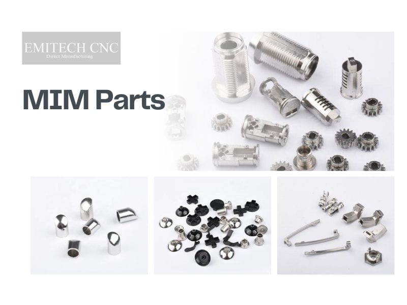
Step 1 – Feedstock Compounding
The MIM process starts with feedstock: a homogeneous mixture of fine metal powder (typically 5–20 µm) and a multi-component binder system. The binder, which usually contains paraffin wax, polypropylene, and surfactants, gives the metal mass thermoplastic flow behavior so it can be injected like plastic.
Compounding is not simple mixing. We use high-shear mixers or twin-screw extruders to coat each powder particle evenly and then pelletize the feedstock into granules. Consistent powder loading—normally 50–65% by volume—is critical. Too little binder causes incomplete filling and powder-binder separation; too much binder leaves excessive porosity after debinding and slows the sintering cycle. At Emitech, every lot is tested for rheology, solids loading, and injection pressure response before it reaches the injection floor.
Feedstock quality also depends on powder morphology. Spherical gas-atomized powder flows better and packs more uniformly than irregular water-atomized powder, which is why most precision MIM applications specify spherical powder. Material choice at this stage determines shrinkage, sintering temperature, and final properties. If you are unsure which alloy fits your application, our MIM materials guide covers stainless steels, low-alloy steels, titanium, and special alloys in detail.
Step 2 – Injection Molding
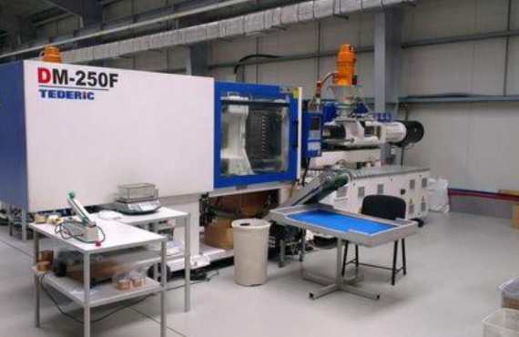
Once the feedstock is qualified, it is fed into a standard injection molding machine fitted with a wear-resistant screw and barrel. The feedstock is heated to 150–200 °C, injected into a precision mold under high pressure—typically 80–150 MPa—and cooled to form the green part.
Injection parameters are tuned for each part: melt temperature, mold temperature, injection speed, holding pressure, and cooling time. If the melt is too cold, the feedstock will not fill thin sections; if too hot, it can degrade the binder and cause blistering during debinding. The green part is roughly 20% larger than the final dimensions to compensate for sintering shrinkage.
Mold design is therefore one of the most knowledge-intensive parts of MIM. Gate location, venting, wall thickness, and draft angles all affect green-part quality. A well-designed MIM mold reduces flash, sink marks, and powder-binder separation, while a poorly designed one creates defects that cannot be corrected later. Emitech designs and builds MIM tooling in-house with shrinkage-compensated cavity dimensions. Typical tooling lead time is 15–25 days depending on complexity and cavity count. Learn more about design rules in our MIM design guidelines.
Step 3 – Debinding
After molding, the green part contains 30–50% binder by volume. Before sintering, most of this binder must be removed to create an open-pore network that allows gases to escape and metal particles to bond. The partially debound part is called the brown part.
Debinding is often the longest step in the MIM cycle, but rushing it causes blistering, cracking, or carbon contamination. The goal is to remove the primary binder while leaving a small amount of backbone polymer that holds the part together until sintering begins.
There are three common debinding methods:
- Solvent debinding: Immerses the green part in a solvent that dissolves the primary wax binder. It is gentle and works well for thin-walled or delicate parts.
- Catalytic debinding: Uses an acid vapor to break down the polymer binder. It is faster than thermal debinding but requires specialized equipment.
- Thermal debinding: Heats the part slowly in a controlled atmosphere to burn out the binder. It is the most common method and is often combined with a pre-sintering step.
The heating profile is tightly controlled. If the binder evaporates too quickly, internal pressure can crack the part. If too slowly, production costs rise. Emitech records weight-loss curves for each debinding batch to verify that the brown part meets the target binder residue before it enters the sintering furnace. For a deeper explanation, read our dedicated article on debinding in MIM.
Step 4 – Sintering
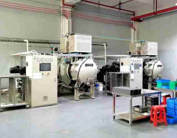
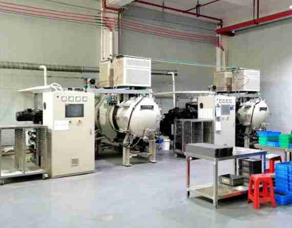
Sintering is the thermal step that transforms the fragile brown part into a solid metal component. The part is heated in a controlled atmosphere—often hydrogen, vacuum, or nitrogen-hydrogen mix—to roughly 80–95% of the alloy’s melting point.
During sintering, metal particles bond through atomic diffusion and neck growth. The part shrinks uniformly by about 15–20% linearly, reaching 95–99% of theoretical density. This shrinkage is why MIM tooling must be scaled up carefully; even small errors in shrinkage assumptions create dimensional rejects.
Atmosphere control is essential. For stainless steels, a reducing atmosphere prevents chromium oxidation. For titanium, high vacuum or argon is required to avoid oxygen and nitrogen pickup. Our sintering process guide explains temperature profiles, furnace types, and defect prevention in more depth.
Step 5 – Post-Processing
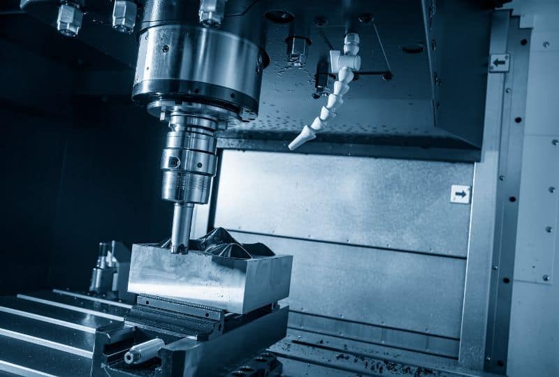
Most MIM parts come out of the furnace at net shape, but some applications require secondary operations to meet tighter tolerances, surface finishes, or assembly requirements. Because MIM produces near-net-shape blanks, secondary machining removes far less material than starting from a solid billet, which lowers both cost and cycle time.
Common post-processing steps include:
- Sizing / coining: Re-pressing the sintered part in a die to improve dimensional precision.
- CNC machining: Drilling, threading, reaming, or turning features that cannot be molded. Emitech offers CNC machining as an integrated secondary service.
- Heat treatment: Hardening, solution annealing, or precipitation hardening to reach specified mechanical properties.
- Surface finishing: Passivation, electropolishing, plating, PVD, shot peening, or tumbling. See our MIM surface treatment page for a full process list.
- Inspection: Dimensional checks by CMM, density testing, metallography, and visual inspection. Our quality inspection process ensures every lot meets the agreed specification.
Because these operations are handled under one roof, Emitech can control cumulative tolerances and reduce logistics delays compared to using separate suppliers.
MIM Process Parameters by Material
The table below summarizes typical sintering conditions and resulting properties for common MIM alloys. Actual values depend on part geometry, powder grade, and furnace atmosphere.
| Material | Sintering Temperature | Atmosphere | Final Density | Typical Hardness | Linear Shrinkage |
|---|---|---|---|---|---|
| MIM 316L | 1,300 – 1,380 °C | H₂ / Vacuum | ≥ 97% | 70–85 HRB | 16–20% |
| MIM 17-4PH | 1,300 – 1,360 °C | H₂ / Vacuum | ≥ 97% | 28–38 HRC (as sintered) | 16–20% |
| MIM 304 | 1,300 – 1,360 °C | H₂ / Vacuum | ≥ 96% | 65–80 HRB | 16–20% |
| MIM 420 | 1,250 – 1,320 °C | Vacuum / N₂-H₂ | ≥ 96% | 50–55 HRC (heat treated) | 15–19% |
| MIM 4605 | 1,120 – 1,250 °C | H₂ / Endogas | ≥ 95% | 30–45 HRC (heat treated) | 14–18% |
| Ti-6Al-4V | 1,200 – 1,300 °C | High vacuum / Ar | ≥ 96% | 30–36 HRC | 14–18% |
Choosing the right material starts with the application environment—corrosion resistance, magnetic response, strength, or biocompatibility. Our engineers can recommend the best alloy and process route during the DFM review.
Design, Tolerances, and Process Control
Successful MIM production depends as much on design as on process execution. Wall thickness should generally be 0.3–10 mm, radii generous, and undercuts avoided unless collapsible cores are justified. Draft angles, gate placement, and shrinkage compensation must be built into the mold from day one. Early design review prevents expensive tooling changes later in the project.
Process control is maintained through documented parameters for each lot: powder lot traceability, molding machine settings, debinding weight loss, sintering temperature profile, and final inspection records. This traceability supports dimensional inspection reports and material certificates, and gives customers confidence in long-term production stability.
Typical MIM tolerances are ±0.3% of dimension or ±0.1 mm, whichever is larger. Tighter tolerances are achievable on critical features through sizing or CNC secondary operations. At Emitech, every new project begins with a design review against our internal DFM checklist, which is aligned with the principles in our MIM design guidelines.
Process control is maintained through documented parameters for each lot: powder lot traceability, molding machine settings, debinding weight loss, sintering temperature profile, and final inspection records. This traceability supports dimensional inspection reports and material certificates.
When MIM Process Steps Deliver the Best Value
MIM is most cost-effective for small-to-medium complex parts produced in volumes of 5,000 to millions per year. It outperforms CNC machining on multi-axis geometries because material waste is low and cycle times are short. Compared to die casting, MIM handles higher-strength alloys and thinner walls without porosity risks from molten metal turbulence.
If your part count is lower or the geometry is simple, machining or stamping may be more economical. Emitech reviews drawings without charge and recommends the most practical route, even if it is not MIM.
Frequently Asked Questions About MIM Process Steps
Q: What are the main MIM process steps?
The five main MIM process steps are feedstock compounding, injection molding, debinding, sintering, and post-processing. Each step must be tightly controlled to achieve final density and dimensional accuracy.
Q: What is a green part in MIM?
A green part is the molded component before debinding. It contains metal powder held together by the thermoplastic binder and is roughly 20% larger than the final sintered dimensions.
Q: What is a brown part in MIM?
A brown part is the component after debinding. Most of the binder has been removed, leaving a porous network of metal particles that is ready for sintering.
Q: How much does MIM shrink during sintering?
Linear shrinkage is typically 15–20%, depending on the alloy, powder loading, and sintering conditions. Tooling is oversized to compensate for this predictable shrinkage.
Q: What debinding methods are used in MIM?
The most common methods are solvent debinding, catalytic debinding, and thermal debinding. The choice depends on part geometry, binder system, and production volume.
Q: What furnace atmosphere is used for sintering MIM?
Stainless and low-alloy steels usually sinter in hydrogen or vacuum. Titanium requires high vacuum or argon to prevent oxygen pickup and embrittlement.
Q: Can MIM parts reach near-full density?
MIM parts typically reach 95–99% of theoretical density. For applications requiring near-full density, hot isostatic pressing (HIP) can be added after sintering.
Q: What secondary operations are common after MIM sintering?
Common operations include CNC machining, sizing, coining, heat treatment, passivation, electropolishing, plating, and visual or CMM inspection.
Q: How long does the MIM process take?
Tooling typically takes 15–25 days. After tool approval, sample parts are usually available in 2–4 weeks and mass production in 4–6 weeks, depending on lot size and finishing requirements. Rush prototypes can sometimes be delivered faster by using soft tooling or shared mold frames.
Q: Why choose Emitech for MIM production?
Emitech manages the complete MIM workflow—from feedstock and tooling to sintering, finishing, and inspection—in one Nanjing facility. This integration reduces lead time, improves quality control, and gives customers a single point of accountability.
Source Custom MIM Parts from Emitech
Nanjing Emitech delivers MIM from tooling through sintering and finishing. Custom MIM parts · MIM services · Request a quote
Last updated: 2026-09-08