
Aluminum Metal Injection Molding (Al-MIM) is a cost-effective manufacturing process that combines plastic injection molding techniques with powder metallurgy to produce complex, lightweight, and high-strength aluminum parts. This process is specifically designed for high-volume production where traditional die casting or CNC machining cannot achieve intricate geometries economically. Recent breakthroughs in two-stage sintering overcome aluminum's oxide barrier, enabling 95-98% density at production volumes above 10,000 units annually.
Explore production capability on our custom MIM parts page, or upload a drawing for a quote.
📋 Executive Summary
The Technology:Two-stage atmospheric sintering overcomes aluminum's persistent oxide barrier through oxygen-rich debinding and nitrogen-atmosphere sintering with magnesium getters.
The Economics:Breakeven at 10,000-20,000 units annually | Tooling is a significant one-time investment that varies with part complexity | Per-part cost drops as volume grows.
The Performance:95-98% final density | 154-310 MPa tensile strength | Properties comparable to wrought 6061-O aluminum.
The Applications:Aerospace (avionics housings, brackets), Automotive (sensor housings, EV components), Consumer Electronics (hinges, structural frames).
The Limitations:Optimal for parts <100g | High initial tooling costs | Requires volumes >10,000 units/year | 12-16 week development timeline.
Reading Time:12 minutes |Technical Level:Intermediate to Advanced
Understanding Aluminum Metal Injection Molding
Aluminum Metal Injection Molding, or Al-MIM, is defined as the convergence of powder metallurgy and plastic injection molding tailored for aluminum alloys. It represents a manufacturing solution that addresses a critical industrial gap: cost-effective production of intricate, three-dimensional aluminum parts that were previously unmanufacturable at scale.
The Industrial Context
Aluminum's density of 2.7 g/cm³ makes it essential for lightweighting strategies across aerospace, automotive, and consumer electronics. However, traditional high-volume aluminum processes face inherent limitations:
Die castingstruggles with:
- Fine features below 0.5mm resolution
- Wall thickness under 1mm
- Complex internal geometries
- Tight dimensional tolerances
CNC machininggenerates:
- 60-90% material waste for complex geometries
- Prohibitive costs at high volumes (>10,000 units/year)
- Extended lead times for intricate features
Al-MIM fills this gap, enablingpart consolidationwhere multi-component assemblies transform into single, integrated components—reducing assembly operations, eliminating fasteners, and lowering total cost of ownership significantly.
The Four-Stage Al-MIM Process
Process Overview:The Al-MIM process is a four-stage manufacturing cycle that transforms fine aluminum powder into dense, solid components through mixing, molding, debinding, and sintering. This sequence typically takes 3-5 days per batch once production is established, ensuring high density and dimensional accuracy.
| Stage | Input | Key Action | Output | Material State |
|---|---|---|---|---|
| 1. Feedstock Prep | Al powder (<25μm) + binders | Mixing, granulation | Feedstock pellets | Metal in polymer matrix |
| 2. Injection Molding | Feedstock pellets | High-pressure injection (50-200 MPa) | Green Part | Solid, 20% oversized |
| 3. Debinding | Green Part | Binder removal (solvent/thermal/catalytic) | Brown Part | Porous, fragile |
| 4. Sintering | Brown Part | Controlled heating (550-600°C) | Final Part | Dense (95-98%) metal |
Watch: Complete overview of the Metal Injection Molding process (5:08 minutes)
Stage 1: Feedstock Preparation
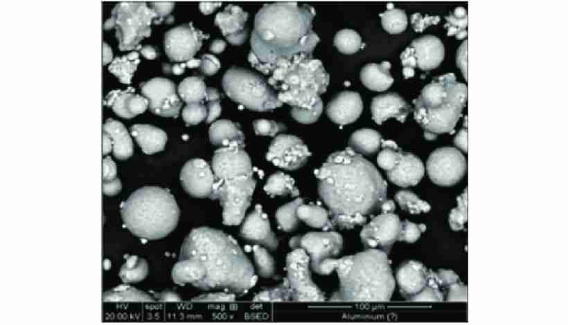
Your process begins with fine aluminum alloy powder, typically gas-atomized to achieve spherical morphology. Particle size remains below 20-25 micrometers—critical for flowability and final density.
Critical Parameters:
| Parameter | Specification | Purpose |
|---|---|---|
| Particle Size | <20-25 μm | Flowability, sintering density |
| Morphology | Spherical | Packing density optimization |
| Powder-to-Binder Ratio | 60:40 by volume | Viscosity control |
| Binder System | Thermoplastics + waxes | Carrier fluid for injection |
The powder mixes homogeneously with multi-component binders (polypropylene, waxes, additives), creating feedstock with plastic-like rheological characteristics. Twin-screw extrusion and pelletization produce material ready for injection molding machines.
Stage 2: Injection Molding
Feedstock pellets load into conventional injection molding machines. Heated barrels (150-200°C) melt the binder component, creating a semi-solid mass that injects under 50-200 MPa pressure into precision-engineered steel molds.
Molding Characteristics:
- Cycle time:30 seconds to 2 minutes per shot
- Cavity fill:Complete within milliseconds
- Green part:Precise geometry, approximately 20% oversized
- Structural integrity:Solidified binder holds particles in position
The green part is solid but relatively weak—handle with care during transfer to debinding.
Stage 3: Debinding
Debinding removes majority binder from green parts, creating interconnected pore networks throughout components. This porosity allows remaining binder constituents to escape during sintering.
⚠️Critical:Inadequate debinding causes binder vaporization during sintering, creating internal pressure that cracks or ruptures parts.
After debinding, you have a fragile, porous "brown part" with backbone polymer maintaining shape.
Three Debinding Methods:
| Method | Time | Advantages | Disadvantages |
|---|---|---|---|
| Solvent | 4-8 hrs | Gentle, controlled | Solvent handling required |
| Thermal | 24+ hrs | No solvent waste | Slow, careful control needed |
| Catalytic | 2-4 hrs | Fastest | Specialized equipment, specific binders |
Stage 4: Sintering - The Critical Transformation
Sintering transforms porous brown parts into dense, solid metal. Parts sit on ceramic or graphite setters in controlled-atmosphere furnaces with precise gas management and temperature control (±5°C accuracy).
Sintering Parameters:
| Parameter | Value | Purpose |
|---|---|---|
| Temperature | 550-600°C | Below Al melting point (660°C) |
| Hold Time | 2-4 hours | Complete densification |
| Heating Rate | 5-10°C/min | Prevent thermal shock |
| Shrinkage | 15-20% linear | Predictable, compensated in mold |
| Final Density | 95-98% theoretical | Near-full densification |
Sintering Sequence:
- Temperature ramp (room temp → 550°C): Remaining binder burns out
- Soak phase (550-600°C, 2-4 hrs): Atomic diffusion at particle contacts
- Densification: Capillary forces drive particle fusion
- Controlled cooling: Prevents thermal stress
Result: High-density components reaching 95-98% of theoretical wrought alloy density with mechanical properties approaching fully dense metal.
Overcoming Aluminum's Fundamental Challenge
The Core Problem:Applying MIM to aluminum required solving material science hurdles that made conventional sintering ineffective. The breakthrough came through sophisticated manipulation of chemistry and thermodynamics.
The Temperature Conflict
Each aluminum particle carries a natural aluminum oxide (Al₂O₃) coating approximately 2-4 nanometers thick. This ceramic-like layer prevents direct metal-to-metal contact necessary for atomic diffusion and particle fusion.
The Critical Dilemma:
Oxide Breakdown Temperature: >1000°C ↕️ (CONFLICT)Aluminum Melting Point: 660°CAl₂O₃ requires extremely high temperatures for breakdown. However, aluminum melts at 660°C. Temperatures needed to disrupt the oxide layer exceed temperatures where your component melts and loses shape.
Additional Complication:Temperature ranges for binder removal (400-500°C) and sintering (550-600°C) overlap. In conventional processes, this leads to carbon residue entrapment, severely degrading mechanical properties.
For decades, this made aluminum MIM commercially impractical.
The Two-Stage Atmospheric Sintering Breakthrough
The patented solution: a two-stage atmospheric process thatdecouples binder removal from oxide reduction.
Phase 1: Oxygen-Rich Atmosphere for Clean Binder Removal
Counter-intuitively, the initial furnace cycle employsoxygen-rich atmosphereat lower temperatures (400-500°C).
Why This Works:
The pre-existing Al₂O₃ layer (2-4 nm thick) protects underlying metal from destructive oxidation. This is the key insight—the oxide layer preventing sintering actually protects metal during binder burnout.
Simultaneously, excess oxygen facilitates complete combustion of carbon-based binders:
Binder (C, H) + O₂ → CO₂ + H₂O (gases escape)This purges carbon without leaving residues that would contaminate final metal.
Phase 1 Parameters:
- Temperature: 400-500°C
- Atmosphere: 20-25% O₂ (oxygen-enriched)
- Duration: 2-6 hours
- Result: Carbon-free brown part with intact Al₂O₃
Phase 2: Nitrogen Atmosphere with Chemical Activators
After complete binder removal, furnace atmosphere shifts to high-purity nitrogen (>99.99%). Temperature increases to sintering range (550-600°C).
The Chemical Activation Mechanism:
Chemical activators in the initial powder blend now activate:
Magnesium (Mg) - The Primary Oxygen Getter:
Magnesium exhibits higher chemical reactivity with oxygen than aluminum. At sintering temperatures, magnesium:
- Vaporizes from strategic furnace locations
- Creates reducing micro-atmosphere around parts
- Reacts with Al₂O₃ on particle surfaces:
3 Mg + Al₂O₃ → 3 MgO + 2 Al (pure aluminum exposed)This reaction breaks down the oxide barrier, exposing pure aluminum and permitting direct particle-to-particle fusion.
Secondary Sintering Aids:
- Tin (Sn):2 wt% addition promotes liquid phase sintering
- Silicon (Si):Enhances sintering kinetics
- Controlled atmosphere:Prevents reoxidation during densification
Phase 2 Parameters:
- Temperature: 550-600°C
- Atmosphere: N₂ (>99.99% purity)
- Duration: 2-4 hours at peak
- Result: Dense (95-98%) aluminum part
This sophisticated chemical approach circumvents the temperature conflict, making high-density aluminum alloy sintering a manufacturing reality.
Strategic Advantages of Al-MIM
Understanding these benefits helps you identify appropriate applications where Al-MIM delivers maximum value.
1. Geometric Complexity and Design Freedom
Unmatched Feature Capability:
Al-MIM delivers geometric complexity rivaling plastic injection molding. You create intricate three-dimensional shapes in a single manufacturing step:
- ✓Undercutswithout secondary operations
- ✓Cross-holes and intersecting channelsmolded directly
- ✓Internal and external threads(M1.0+) as-molded
- ✓Fine surface textures(knurling, logos) integrated
- ✓Variable cross-sectionsand complex contours
- ✓Thin wallsdown to 0.5mm thickness
Part Consolidation: The Hidden Value
Multiple components requiring separate manufacturing and assembly can redesign into single, monolithic MIM parts.
Example - Automotive Sensor Housing:
Traditional:Main body (die cast) + bracket (stamped/welded) + threaded inserts + cover (machined/fastened) = 4 components, 6 operations, 8 fasteners
Al-MIM:Single integrated component with molded threads and mounting features = 1 component, 0 assembly operations, 0 fasteners
Consolidation Benefits:
- significant assembly cost reduction
- meaningful weight reduction
- Improved reliability (fewer interfaces)
- Simplified supply chain
2. Lightweighting Performance
Al-MIM combines MIM's geometric capabilities with aluminum's low density (2.7 g/cm³).
Achieved Properties:
| Property | Al-MIM Achievement | Significance |
|---|---|---|
| Final Density | 95-98% theoretical | Near-full densification |
| Grain Structure | Fine, equiaxed (<50 μm) | Uniform, isotropic properties |
| Porosity | 2-5% isolated micropores | Minimal impact on most applications |
Performance Impact:
Foraerospace: Every gram saved translates to fuel savings, increased payload, extended range.
Forautomotive: 10% vehicle weight reduction → 6-8% fuel economy improvement; critical for EV range optimization.
Forportable electronics: Improved user experience, extended battery life, premium aesthetics.
3. Economic Viability at Production Volumes
While initial tooling investment is substantial and varies with part complexity, the process becomes exceptionally cost-effective for high-volume production.
Economic Breakpoint:
| Annual Volume | Tooling (3-yr amortized) | Processing | Total/Part |
|---|---|---|---|
| 10,000 | High | Moderate | Higher at low volume |
| 25,000 | Moderate | Lower | Mid-volume |
| 50,000 | Low | Low | Competitive |
| 100,000 | Very low | Low | Very competitive |
Cost Savings Drivers:
- ✓Near-net-shape manufacturingminimizes secondary machining (eliminates 4-8 CNC operations)
- ✓Part consolidationeliminates assembly (significant per-assembly savings)
- ✓Material efficiencyreduces waste from 60-90% (machining) to <5% (MIM)
- ✓Simplified supply chainreduces inventory andlogistics costs
For complex parts at volumes exceeding 50,000 annually: substantial total cost savings versus machine-from-billet approach.
4. Material Efficiency and Sustainability
Material Utilization Comparison:
| Process | Utilization | Waste | Environmental Impact |
|---|---|---|---|
| Al-MIM | 95-98% | 2-5% (recyclable) | Minimal waste generation |
| CNC Machining | 10-40% | 60-90% (chips) | High waste, energy for reprocessing |
| Die Casting | 85-90% | 10-15% (runners) | Moderate, fully recyclable |
Environmental Benefits:
At 50,000 parts/year, Al-MIM saves approximately 2,000-4,000 kg aluminum waste compared to machining. Combined with aluminum's infinite recyclability and reduced energy for eliminated machining operations, Al-MIM typically shows 30-50% lower carbon footprint than machining for complex parts.
Mechanical Properties and Performance
Understanding achieved properties is essential for determining suitability in load-bearing applications.
Density and Microstructure
Achieved Density: 95-98% of Theoretical
Finished Al-MIM components reach near-full densification. Remaining 2-5% consists of fine, isolated, well-rounded microporosity (1-10 μm size).
Microstructural Features:
- Grain size: 20-50 μm (fine, equiaxed)
- Grain structure: Uniform throughout volume
- Porosity: Isolated spherical pores
- Directional properties: Isotropic (uniform in all directions)
⚠️Engineering Note:While 95-98% density is excellent for powder metallurgy, residual porosity can act as stress concentrators in very high cycle fatigue applications (>10⁷ cycles). For most structural applications, this distinction is not significant.
Tensile Strength and Performance Benchmarks
Published performance data for successfully developed Al-MIM alloys:
| Property | Al-MIM (Al-Si) | Al-MIM (6061) | Wrought 6061-O | Wrought 6061-T6 |
|---|---|---|---|---|
| Density (g/cm³) | 2.58 (95.5%) | 2.64 (97.5%) | 2.70 (100%) | 2.70 (100%) |
| UTS (MPa) | 154 | 250-280 | 124 | 310 |
| Yield (MPa) | — | 210-240 | 55 | 276 |
| Elongation (%) | — | 8-12 | 25-30 | 12-17 |
| Hardness | 58 HBW | 85-92 HRB | 30 HBW | 95 HBW |
| vs. Wrought T6 | 50% | 80-85% | 40% | 100% |
Performance Context:
Al-MIM properties generally matchannealed wrought aluminum(O-temper). With T6 heat treatment post-sintering, properties reach 80-90% of wrought 6061-T6 strength—sufficient for most applications but representing a trade-off: you gain geometric complexity but sacrifice ultimate material strength versus optimally heat-treated wrought aluminum.
Heat Treatment Response
Al-MIM parts respond to standard aluminum heat treatments:
T6 Treatment(Solution heat treatment + artificial aging):
- Process: Heat to 530°C, quench, age at 160-180°C for 8-18 hours
- Results: Tensile strength increases 40-60% over as-sintered
- Final properties: Approach 80-90% of wrought 6061-T6
Heat treatment is performed after sintering and any necessary machining operations.
Applications Across Key Industries
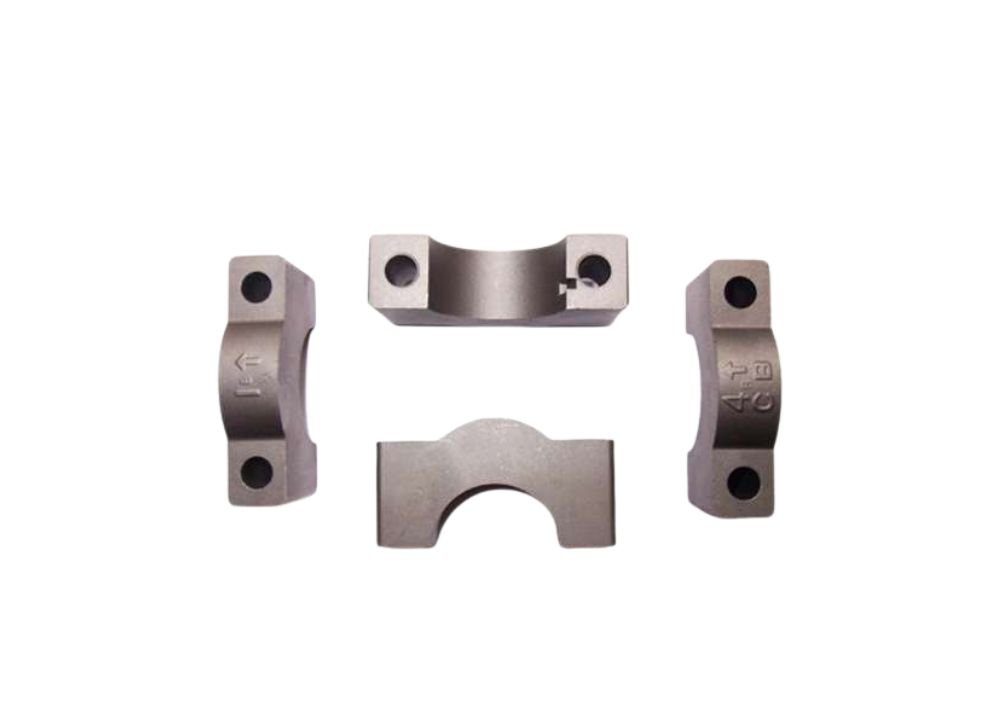
Primary adoption driver: producing lightweight, complex-shaped components in high volumes where traditional methods fail or become cost-prohibitive.
Aerospace and Defense
Weight reduction directly impacts fuel efficiency, payload capacity, and performance. Al-MIM suits intricate non-structural or semi-structural components requiring high strength-to-weight ratios.
Key Components:
- Avionics housings:Lightweight enclosures for navigation systems, EMI shielding
- Connectors and fittings:Hydraulic/pneumatic connectors with molded threads, multi-port manifolds
- Guidance systems:Fin assemblies, canard structures, gimbal components
- Engine/fuel systems:Fuel injector nozzles, sensor housings, heat sink components
Requirements:30-50% weight reduction vs. steel; operating temperatures -55°C to +125°C; program-specific quality documentation.
Automotive Sector
Continuous pressure for fuel economy and emissions reduction makes lightweighting central to vehicle design.
Key Components:
- Powertrain:VVT actuator housings, rocker arm assemblies, shift lever mechanisms
- Fuel/emissions systems:Fuel rail connectors, evaporative emissions components, sensor housings
- Chassis/body:Steering column brackets, seat mechanisms, suspension sensor mounts
- Electric vehicle:Battery housing brackets, BMS housings, motor mounts, charging port components
Volume Economics:Typical automotive volumes (50,000-500,000 per platform over 5-7 years) match perfectly with Al-MIM economics.
Consumer Electronics
Trends toward smaller, lighter devices create demand for high-precision, complex metal parts with premium aesthetics.
Key Components:
- Mobile devices:Smartphone hinges (especially foldables), internal structural frames, camera mounts
- Wearables:Smartwatch cases with integrated lugs, fitness tracker housings, clasp mechanisms
- Computing:Laptop hinge assemblies, tablet brackets, heat dissipation components
Design Drivers:Aesthetic requirements (premium finish), miniaturization (often <10g weight), integration (multiple functions in single component).
Medical Devices
Complex, miniaturized components requiring high precision. Al-MIM offers advantages for non-implantable devices where light weight matters.
Key Components:
- Surgical instruments:Lightweight handles for extended procedures, internal mechanisms for laparoscopic tools
- Diagnostic equipment:Portable device housings, sample handling mechanisms
- External devices:Prosthetic limb components where mass reduction improves user comfort
Regulatory:FDA registration, ISO 13485 quality systems, biocompatibility testing for patient contact, sterilization compatibility required.
When to Choose Al-MIM: Comparative Analysis
Understanding where Al-MIM excels versus alternatives is critical for informed decisions.
| Feature | Aluminum MIM | Die Casting | CNC Machining |
|---|---|---|---|
| Process Type | Near-net-shape (sintering) | Net-shape (molten metal) | Subtractive (removal) |
| Complexity | Very High | Moderate-High | Very High |
| Wall Thickness | 0.5-3mm optimal | 1-6mm | Unlimited |
| Tooling Cost | Varies | Varies | None |
| Per-Part (High Vol) | Varies | Varies | Varies |
| Optimal Volume | 10K-500K/year | 50K-1M+/year | 1-10K/year |
| Material Waste | <5% | 10-15% | 60-90% |
| Porosity | 2-5% isolated | Can be significant | None |
| Tolerances | ±0.3-0.5% | ±0.5% | ±0.01mm |
| Lead Time | 12-16 weeks initial | 10-14 weeks initial | Days |
Al-MIM vs. Die Casting
Complexity and Feature Resolution:
Al-MIM advantages:
- Thinner walls (0.5mm vs. 1mm+ for die casting)
- Finer features (0.2mm details achievable)
- Better for small parts (<100g)
- Molded threads and surface textures
- Superior for intricate internal passages
Die casting advantages:
- Larger parts (no practical upper limit)
- Faster cycle times (seconds vs. days for MIM)
- Lower per-part costs at very high volumes (>500,000)
- Better for thick sections
Material Properties - The Porosity Factor:
High-pressure molten metal injection in die casting can trap gases, creating porosity (1-10% depending on control). Al-MIM's debinding stage allows complete gas escape, resulting in lower porosity (2-5% isolated) and better fatigue properties for high-cycle applications.
🔧 YOUR DECISION POINT: Al-MIM vs. Die Casting
Choose Al-MIM when you have:
- ✓ Parts under 100g weight
- ✓ Wall thickness <2mm
- ✓ Complex internal features or cross-holes
- ✓ Fine details or molded threads
- ✓ Volumes: 10,000-500,000 annually
- ✓ Porosity-sensitive applications (fatigue loading)
Choose Die Casting when you have:
- ✓ Parts over 100g weight
- ✓ Simpler geometries
- ✓ Volumes >500,000 annually
- ✓ Cost per part is paramount
- ✓ Faster time-to-market required
Al-MIM vs. CNC Machining
Material Efficiency:
Al-MIM:95-98% utilization, minimal waste (2-5% recyclable)
CNC Machining:10-40% utilization for complex parts, 60-90% becomes chips requiring energy-intensive reprocessing
Volume Economics:
| Annual Volume | Al-MIM Total | CNC Cost | Advantage |
|---|---|---|---|
| 5,000 | Varies | Varies | CNC wins |
| 10,000 | Varies | Varies | Breakeven |
| 25,000 | Varies | Varies | Al-MIM wins (52% savings) |
| 50,000 | Varies | Varies | Al-MIM wins (69% savings) |
Complexity Impact:
In CNC machining, complexity significantly increases cycle time and cost (simple bracket: 15 min vs. complex manifold: 2-4 hrs). In MIM, complexity builds into mold and doesn't add to per-part costs—a critical distinction for intricate components.
Precision Requirements:
CNC machining:Achieves ±0.01-0.05mm tolerances consistently, surface finish to Ra 0.4 μm
Al-MIM:Standard tolerances ±0.3-0.5%, can achieve ±0.1mm on critical features with post-machining, as-sintered Ra 0.8–1.6 µm
🔧 YOUR DECISION POINT: Al-MIM vs. CNC Machining
Choose Al-MIM when you have:
- ✓ Volumes >10,000 units/year
- ✓ Complex geometries (>5 CNC operations)
- ✓ Thin walls or intricate internal features
- ✓ 3-5+ year production lifecycle
- ✓ Material waste is a concern
- ✓ Standard tolerances acceptable
Choose CNC Machining when you have:
- ✓ Low volumes (<10,000 units/year)
- ✓ Prototyping or design iteration
- ✓ Extremely tight tolerances required (±0.01mm)
- ✓ Simple to moderate geometries
- ✓ Quick turnaround needed (days not months)
Key Limitations and Design Considerations
Understanding limitations defines Al-MIM's specific manufacturing niche and guides proper process selection.
Economic Constraints
Initial Investment:substantial (covering tooling, development, and testing)
Volume-Cost Relationship:
Al-MIM becomes cost-competitive at10,000-20,000 units annuallywith production lifecycles extending3-5+ years. Below these thresholds, alternatives typically offer better economics.
When Al-MIM is NOT Economical:
- ✗ Low-volume production (<10,000 units/year)
- ✗ Rapid prototyping requirements (weeks not months)
- ✗ Short product lifecycles (<2 years)
- ✗ Uncertain demand forecasts
Physical and Geometric Constraints
Size Limitations:
Optimal range:0.1g to 100g per part
Maximum practical:250g per part
Why these limits:
- Upper constraint:Debinding becomes difficult for thick sections (>10mm), requiring 48-72+ hours; handling large fragile brown parts without distortion; sintering uniformity challenges in large parts.
- Lower constraint:Handling difficulties with tiny parts; mold fabrication challenges for micro-features.
Critical Design Principles
1. Uniform Wall Thickness (Most Important)
Recommended:Maintain consistent wall thickness throughout
Target range:1-4mm optimal
Variation limit:±20% maximum
Why critical:Significant thickness variations cause differential shrinkage rates, internal stress concentrations, warpage during sintering, and potential cracking.
2. Generous Radii and Draft
Minimum internal radius:0.5mm (preferably 1mm+)
Draft angles:0.5-1° per side
Sharp corners create stress concentrations and accelerate tool wear.
3. Shrinkage Management
Linear shrinkage:15-20% in each dimension
Volumetric shrinkage:Up to 30%
This substantial shrinkage must be precisely predicted and compensated in mold design. Most programs require 1-2 tool iteration cycles to achieve target dimensions, adding 4-8 weeks and substantial cost to development.
Process Constraints
Tool Life:150,000-300,000 shots (vs. 1M+ for die casting) due to abrasive powder feedstock
Process Chain Integrity:Multi-stage nature means errors at any stage cascade to final part defects. Requires statistical process control and rigorous quality management.
Development Timeline:12-16 weeks typical from design to production-ready parts
Material Selection: Aluminum Alloys for MIM
Not all aluminum alloys work effectively in MIM. Understanding which alloys have been successfully developed guides material selection.
6061 Aluminum Alloy: The Industry Standard
6061 (Al-Mg-Si system) has emerged as the most successful aluminum alloy for MIM applications.
Chemical Composition:
| Element | Weight % | Purpose |
|---|---|---|
| Aluminum | 95.8-98.6 (balance) | Base metal |
| Magnesium | 0.8-1.2 | Aids oxide reduction, precipitation hardening |
| Silicon | 0.4-0.8 | Sintering aid, fluidity |
| Copper | 0.15-0.4 | Strength enhancement |
| Chromium | 0.04-0.35 | Grain refinement |
Why 6061 Excels for MIM:
- ✓Magnesium contentaids oxide layer reduction during two-stage sintering
- ✓Siliconprovides fluidity during liquid-phase sintering
- ✓Responds well to heat treatment(T4, T6) for strengthening
- ✓Balanced properties:Good strength, ductility, corrosion resistance
- ✓Extensive research database:Well-characterized for MIM
Typical Properties:
As-sintered:
- Density: 95-98% theoretical
- Tensile strength: 180-220 MPa
- Elongation: 10-15%
After T6 heat treatment:
- Tensile strength: 250-310 MPa (approaching wrought 6061-T6)
- Yield strength: 210-275 MPa
- Elongation: 8-12%
Alternative Alloy Systems
Hypereutectic Al-Si Alloys:
- Composition: 12-18% Si with Mg/Sn sintering aids
- Achieved: 95.5% density, 154 MPa tensile strength
- Applications: Wear-resistant components, high thermal conductivity parts
Al-Cu Alloys (2xxx analogs):
- Under development for higher strength
- Current: 200 MPa strength at 93% density
- Challenge: Reduced corrosion resistance vs. 6061
Pure Aluminum:
- Feasible but limited structural capabilities
- Applications: Electrical/thermal conductivity where strength isn't critical
Quality Control and Testing
Ensuring consistent quality requires comprehensive testing protocols.
Critical Parameters
1. Density Verification (Most Critical)
Target:Minimum 95% theoretical (preferably 96-98%)
Measurement:Archimedes' principle (water displacement) - ASTM B962
Why critical:Below 95%, properties degrade significantly due to interconnected porosity
2. Dimensional Accuracy
Standard tolerances:±0.3-0.5%
With post-machining:±0.05-0.1mm on critical features
Measurement:CMM for complex geometries, micrometers/calipers for simple dimensions
3. Mechanical Testing
Tensile testing (ASTM E8):
- Measures: UTS, yield strength, elongation
- Acceptance: Must meet material specification (typically 80% of wrought properties)
Hardness testing:
- Methods: Vickers, Rockwell B, Brinell
- Frequency: Every production lot
- Benefit: Quick assessment of heat treatment effectiveness
Industry Standards
Quality Management Systems:
- Industry-specific QMS:Automotive and aerospace programs define additional quality management requirements
- ISO 13485:Medical device quality systems
Material Specifications:
While no standards exist exclusively for Al-MIM, adapt relevant wrought aluminum standards (ASTM B, AMS specifications) and document equivalency through testing.
Frequently Asked Questions
Q: Q1: What is the minimum order quantity for aluminum MIM parts?
Economic breakeven typically occurs at10,000-20,000 parts annuallydue to tooling costs (which vary widely). Many suppliers require initial orders of 5,000-25,000 parts.
For validation, some suppliers offer limited runs (100-1,000 parts) at premium pricing using soft tooling, but per-part costs can be 10-20x higher than production volumes.
Volume guidance:
- 1-1,000 parts: Use CNC machining or 3D printing
- 1,000-10,000 parts: Breakeven zone—detailed analysis required
- 10,000-50,000 parts: Al-MIM becomes competitive
- 50,000+ parts: Al-MIM offers significant cost advantages
Q: Q2: Can aluminum MIM parts be heat treated?
Yes.Aluminum MIM parts respond to standard heat treatments:
T6 Treatment(most common):
- Process: Heat to 530°C, quench, age at 160-180°C for 8-18 hours
- Results: Tensile strength increases 40-60% over as-sintered
- Final properties: Reach 80-90% of wrought 6061-T6
Heat treatment is performed after sintering and any machining operations. Some ductility reduction (20-30%) occurs in T6 condition vs. as-sintered.
Q: Q3: What tolerances can aluminum MIM achieve?
Standard as-sintered:±0.3% to ±0.5% of nominal dimension
Examples:
- 10mm feature: ±0.03-0.05mm
- 50mm dimension: ±0.15-0.25mm
For tighter tolerances:Strategic post-machining of critical features can achieve ±0.05-0.1mm.
Comparison:
- CNC machining: ±0.01-0.05mm routinely
- Die casting: ±0.5% typical
- Al-MIM: ±0.3-0.5% standard
Design recommendation:Design with standard MIM tolerances; specify secondary operations only for truly critical dimensions.
Q: Q4: Why is aluminum more challenging than steel for MIM?
Three fundamental challenges:
1. The Oxide Barrier:Each aluminum particle has a stable Al₂O₃ layer requiring >1000°C to break down, but aluminum melts at 660°C—creating an impossible temperature conflict. Steel's oxide layers break down more easily.
2. Narrow Process Window:Aluminum's 660°C melting point creates a narrow sintering window (550-600°C—only 60-110°C margin). Steel melts at 1400-1450°C, allowing sintering at 1250-1350°C—much wider margin.
3. Overlapping Temperatures:Binder removal (400-500°C) and sintering (550-600°C) overlap for aluminum, risking carbon entrapment. Steel's clear separation (binder removal 400-600°C, sintering 1250-1350°C) allows clean processing.
The solution:Two-stage atmospheric sintering specifically addresses aluminum's challenges through oxygen-rich debinding followed by nitrogen-atmosphere sintering with magnesium getters.
Q: Q5: What industries use aluminum MIM most?
Primary adopters:
Aerospace and Defense (20-25%):Avionics housings, connectors, guidance system components, fuel system parts. Driver: Weight reduction paramount—every gram impacts fuel efficiency and payload.
Automotive (30-35%):Engine/transmission components, sensor housings, EV battery parts, power electronics. Driver: Fuel economy regulations and EV range optimization demand lightweighting.
Consumer Electronics (25-30%):Smartphone hinges, wearable housings, internal frames, camera mounts. Driver: Miniaturization requires complex micro-structures with premium aesthetics.
Medical Devices (5-10%):Surgical instrument components, diagnostic equipment, prosthetic elements. Driver: Lightweight precision improves ergonomics and patient comfort.
Common thread: All needlightweight + geometric complexity + production volumeswhere traditional manufacturing fails or is cost-prohibitive.
Q: Q6: How long does aluminum MIM development take?
Initial Development Timeline:
| Phase | Duration |
|---|---|
| Design & Feasibility | 2-4 weeks |
| Tooling Design | 2-3 weeks |
| Mold Fabrication | 6-12 weeks |
| Process Development | 2-4 weeks |
| Sintering Optimization | 2-3 weeks |
| First Article Validation | 1-2 weeks |
| Total | 15-28 weeks (4-6 months typical) |
Production Cycle Time:
- Injection molding: 30 sec - 2 min per shot
- Debinding: 12-48 hours
- Sintering: 24-48 hours
- Total per-part cycle:3-5 days
Once in production, throughput is excellent: 1,000-16,000+ parts per week depending on mold cavities and furnace capacity.
Q: Q7: Is aluminum MIM environmentally sustainable?
Yes, several advantages:
Material Efficiency (Primary):
- Al-MIM: 95-98% utilization vs. CNC machining: 10-40%
- At 50,000 parts/year: Saves 2,000-4,000 kg aluminum waste
Energy Considerations:
- Al-MIM: ~0.7-1.4 kWh per part
- CNC machining: ~2.8-5.5 kWh per part (including embedded energy in wasted material)
- Advantage: 40-60% less total energy at volume
Aluminum Recyclability:
- Infinite recycling without property degradation
- Recycling uses only 5% of energy vs. primary production
Operational Emissions:
- Lightweight components in vehicles: 10% weight reduction → 6-8% fuel economy improvement
- Over vehicle lifetime: Saves 1,500-3,000 kg CO₂ emissions
Comprehensive lifecycle assessment:Al-MIM shows 30-50% lower carbon footprint than machining for complex parts at volumes >25,000 annually.
Q: Q8: What are typical costs and when is it economical?
Initial Investment:substantial (tooling, development, testing)
Per-Part Costs at Volume:
| Annual Volume | Total Cost/Part |
|---|---|
| 10,000 | Varies |
| 25,000 | Varies |
| 50,000 | Varies |
| 100,000 | Varies |
Economic Breakeven:
vs. CNC Machining:10,000 units/year
Strong economic case:25,000+ units/year (52-78% cost savings)
Optimal range:25,000-500,000 units/year
Requirements:
- 3-year lifecycle minimum for ROI
- 5+ year lifecycle: Excellent economics
- <2 year lifecycle: High risk
Part complexity multiplier:
- Complex parts (many CNC operations): Economic at lower volumes (5K-10K)
- Simple parts: Higher threshold needed (15K-20K)
Q: Q9: Can aluminum MIM replace my current process?
It depends on your specific requirements.
Strong Replacement Candidates:
- ✓ Complex geometries requiring 5+ CNC operations
- ✓ Multi-part assemblies that can consolidate
- ✓ High volumes (>10K/year) with stable 3-5+ year demand
- ✓ Thin-walled structures (<3mm) where weight matters
- ✓ Standard tolerances acceptable (±0.3-0.5%)
Poor Replacement Candidates:
- ✗ Low volumes (<10K/year) ✗ Very large parts (>250g)
- ✗ Extremely tight tolerances throughout (±0.01mm)
- ✗ Simple geometries
- ✗ Short lifecycles (<2 years)
Evaluation Framework:
Score your application (1 point each):
- Annual volume >10K units? (+1)
- Production lifecycle >3 years? (+1)
- Requires >5 CNC operations? (+2)
- Thin walls or intricate features? (+1)
- Multiple parts could consolidate? (+2)
- Standard tolerances acceptable? (+1)
- Part size <100g? (+1)
8-9 points:Excellent candidate - proceed
5-7 points:Good candidate - conduct TCO analysis
3-4 points:Marginal - likely better alternatives
0-2 points:Poor candidate - not recommended
Recommendation:Always conduct thorough technical and economic analysis specific to your requirements before committing to process transition.
Q: Q10: What development timeline should I expect?
Realistic Timeline Breakdown:
Months 1-2 (Weeks 1-8):
- Design for MIM optimization
- Tooling design and procurement
- Material selection and feedstock development
Months 2-4 (Weeks 9-16):
- Mold fabrication (longest lead item)
- Process parameter development
- Initial molding and debinding trials
Months 4-5 (Weeks 17-20):
- Sintering optimization
- First article production
- Property validation and testing
Month 5-6 (Weeks 21-24):
- Tool adjustments if needed (common)
- Production validation runs
- Customer approval and release
Total: 4-6 months typicalfrom program start to production-ready parts
Critical path:Mold fabrication (6-12 weeks) is typically the longest lead item. Consider this in your project planning.
Risk mitigation:Some suppliers offer soft tooling or 3D-printed molds for faster validation (2-4 weeks) before committing to production steel molds.
Q: Which aluminum alloys can be processed with MIM?
A: The most established AlMIM alloys are 6061 and 2014, with 7075 and Al-Si alloys available for higher-strength or fluidity-critical designs. Because aluminum sinters in a narrow window below its 660 °C melting point, alloy and powder specification must be matched to the furnace atmosphere — typically high-purity nitrogen — to avoid distortion.
Q: Why is aluminum MIM more difficult than steel MIM?
A: Aluminum powder carries a tenacious oxide layer that blocks diffusion bonding, so AlMIM requires magnesium or tin sintering aids, tight dewpoint control, and precise temperature windows. The process window is far narrower than for stainless steels, which is why only specialized MIM suppliers offer aluminum — and why design review should start earlier.
Conclusion
Aluminum Metal Injection Molding has overcome fundamental material science barriers through the innovative two-stage atmospheric sintering process. This breakthrough enables cost-effective, high-volume production of small, lightweight aluminum components with geometric complexity that other scalable methods cannot achieve.
Your Value Proposition:
For industries driven by lightweighting and design complexity—aerospace, automotive, consumer electronics—Al-MIM represents a critical enabling technology. It bridges the gap between design aspiration and manufacturing reality, unlocking design possibilities through part consolidation that reduces assembly operations, eliminates fasteners, and improves product reliability.
The Strategic Fit:
Consider Al-MIM when your application requires:
- ✓ Complex 3D geometries with integrated features
- ✓ Parts under 100 grams (up to 250g maximum)
- ✓ Production volumes exceeding 10,000 units annually
- ✓ Weight reduction as a critical design driver
- ✓ Standard tolerances (±0.3-0.5%) acceptable
- ✓ Stable production lifecycle of 3-5+ years
Understanding the Constraints:
Success requires accepting limitations:
- High initial tooling investment (which varies widely)
- 12-16 week development timeline
- Size constraints (optimal <100g)
- Properties typically 80-90% of peak-aged wrought aluminum
- Process complexity requiring specialized expertise
The Reality:
Aluminum MIM occupies a specific, valuable manufacturing niche. It's not universal, but when requirements align—complex geometry, appropriate volumes, acceptable properties—Al-MIM delivers solutions unavailable through alternative processes.
Your competitive advantage comes from strategically deploying Al-MIM where its unique capabilities create maximum value: transforming complex, multi-part assemblies into integrated, lightweight, high-performance components that define next-generation products.
This technical analysis draws on published research, industry data, and manufacturing process expertise to provide engineering-focused guidance for design and sourcing decisions. Always conduct application-specific feasibility studies and consult with qualified Al-MIM suppliers for your particular requirements.
Precision Metal Parts from Emitech
Nanjing Emitech delivers MIM, CNC machining, and custom metal parts. MIM services · Request a quote
Last updated: 2026-07-23
Continue reading
- Metal Injection Molding vs. Die Casting—Which Is Best for Your Manufacturing Needs?
- Metal Injection Molding vs. Stamping: Choosing the Best Process for Your Parts
- Metal Injection Molding with Hot Isostatic Pressing: Complete Engineering Guide to Achieving 99.9% Density
- Metal Powder Sintering Temperature Guide: Optimal Settings for Different Alloys