
MIM vs Die Casting: Process Comparison
Quick Answer
MIM excels at small, complex parts (0.1–200 g) in stainless steel, titanium, and tool steels with typical tolerances of ±0.3%, while die casting produces larger aluminum, zinc, or magnesium components (30 g–10 kg+) at lower unit cost above ~100,000 units annually. Your part size, material, complexity, and confirmed production volume determine the optimal process. See our MIM services and DFM guidelines when evaluating a new design.
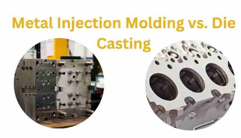
Quick Decision Guide: Which Process Fits Your Needs?
| Your Requirement | Choose MIM | Choose Die Casting |
|---|---|---|
| Part Weight | 0.1-200g | 30g-10kg+ |
| Complexity Level | High (thin walls, undercuts, fine details) | Moderate (standard geometries) |
| Material Type | Stainless steel, titanium, tool steel | Aluminum, zinc, magnesium |
| Annual Volume | 10,000-50,000 units | 100,000+ units |
| Tolerance | ±0.3% | ±0.1-0.3mm |
| Surface Finish | Ra 0.8–1.6 µm (typical as-sintered) | Ra 1.6-3.2μm (excellent as-cast) |
| Tooling Cost | Lower initial investment | Higher initial investment |
| Per-Part Cost | Higher at low volume | Lower at high volume |
| Mold Life | 150K-300K shots | 1M+ shots |
Understanding the Core Differences
Metal Injection Molding and Die Casting both inject material into molds under pressure, but their fundamental approaches create dramatically different capabilities.
Metal Injection Molding (MIM): Powder-Based Precision
MIM uses fine metal powders (60% by volume) mixed with thermoplastic binders (40%) to create moldable feedstock. This powder-based approach enables complex geometries impossible with molten metal.
The Process:
- Injection→ Feedstock injected into molds creates "green" parts
- Debinding→ Binder removed, leaving porous metal skeleton
- Sintering→ High-temperature fusion creates dense components (96-99% density)
- Finishing→ Optional machining or surface treatment
💡Key Characteristic:Parts experience 15-20% linear shrinkage during sintering, requiring sophisticated mold design to compensate.
Watch: Metal Injection Molding Process Explained
Metal Injection Molding manufacturing process explained
Die Casting: Molten Metal at High Pressure
Die casting injects molten metal at 10-175 MPa into hardened steel dies. The metal rapidly solidifies into the die's shape.
The Process:
- Melting→ Metal heated to liquid state
- Injection→ Molten metal forced into die under high pressure
- Cooling→ Rapid solidification in seconds to 30 seconds
- Ejection→ Part removed and trimmed
💡Key Characteristic:Minimal shrinkage (0.007"/inch) makes dimensional control straightforward.
Watch: Die Casting Manufacturing Process
Die casting aluminum manufacturing process
Material Capabilities: The Fundamental Dividing Line
Your material requirements often eliminate one process immediately.
MIM Material Range
Ferrous Alloys (MIM's Exclusive Territory):
- Stainless steel (316L, 17-4PH, 420)
- Tool steel for wear resistance
- Low-alloy steel for strength
High-Performance Alloys:
- Titanium and titanium alloys (aerospace)
- Cobalt-chrome (medical implants)
- Nickel-based superalloys (high temperature)
💡MIM Advantage:Can process high-melting-point materials without handling molten metal—critical for ferrous alloys and specialty materials.
Die Casting Materials
Non-Ferrous Alloys Only:
- Aluminum alloys (A380, A383) → lightweight, thermal conductivity
- Zinc alloys (Zamak 3, 5) → excellent castability, low cost
- Magnesium alloys (AZ91D) → ultra-lightweight
- Copper alloys → electrical conductivity
⚠️Critical Limitation:Die casting cannot process ferrous metals economically. High melting points destroy molds, reducing die life from 1M+ shots to 50K or less.
Decision Point:Need steel, titanium, or specialty alloys? → MIM is your only viable option.
Part Size and Complexity: Where Each Process Excels
MIM: Small Parts with Complex Geometries
Optimal Size Range:0.1-200g (sweet spot: 15-20g)
Complexity Capabilities:
- Wall thickness as thin as 0.1-0.2mm
- Complex undercuts without requiring slides
- Internal channels and passages
- Fine threads molded directly
- High-aspect-ratio features
- Consolidation of multiple parts into single piece
The powder-binder feedstock flows into intricate cavities easily and doesn't require the part to be ejected while rigid—the binder holds shape until sintering. This is why MIM handles geometric complexity that die casting requires expensive slide mechanisms to achieve.
Die Casting: Medium to Large Parts
Optimal Size Range:30g to 10kg+
Complexity Capabilities:
- Moderate geometric complexity
- Standard undercuts and features
- Good surface area coverage
- Structural components with ribs and bosses
Limitations:
- Very thin walls (<1mm) risk incomplete fill
- Extreme undercuts require complex tooling (slides, collapsible cores)
- Fine internal features challenging due to molten metal flow characteristics
📊Size Decision Rule:
- Under 200g + complex features → MIM
- Over 200g + moderate complexity → Die Casting
- 50-200g gray zone → Evaluate complexity and material
Dimensional Accuracy and Surface Quality
MIM Tolerances and Finish
Typical Tolerances:±0.3% of nominal dimension
Example on 50mm dimension:
- As-sintered: ±0.15mm
- With tight process control: ±0.05-0.15mm
- With secondary machining: ±0.025mm
Surface Finish:Ra 0.8–1.6 µm achievable as-sintered
The 15-20% linear shrinkage during sintering requires sophisticated mold design with compensation factors, and shrinkage is not perfectly uniform across complex geometries. Secondary machining is often needed for critical dimensions.
Die Casting Tolerances and Finish
Typical Tolerances:±0.1-0.3mm depending on size
Example on 50mm dimension:
- As-cast: ±0.15mm
- With process control: ±0.08mm
- With secondary machining: ±0.02mm
Surface Finish:Ra 1.6-3.2μm as-cast
Minimal shrinkage means predictable dimensional outcomes, simpler mold design, and excellent consistency across production runs—often no secondary operations needed.
💡Tolerance Winner:Die casting offers more predictable dimensional control. MIM can achieve tight tolerances but requires more sophisticated process control.
Production Economics: Where Cost Differences Matter
Tooling Investment
MIM Tooling:Lower initial investment
- Injection molds with shrinkage compensation
- Mold life: 150,000-300,000 shots
- Lower initial investment, more frequent replacement
Die Casting Tooling:Higher initial investment
- Hardened steel dies for extreme conditions
- Mold life: 1,000,000+ shots (3-7× longer than MIM molds)
- Higher upfront cost, amortizes well at volume
Per-Part Production Costs
At 10,000 units, die casting often has a lower per-part cost than MIM because of faster cycle times (seconds vs. days for MIM batch processing), fewer processing steps, and lower raw material cost (ingots vs. powder).
Volume Break-Even Analysis
MIM Economic Range:10,000-50,000 units annually—lower tooling cost justifies higher per-part cost, and complex parts requiring extensive machining if die cast may favor MIM even at lower volumes.
Die Casting Economic Range:100,000+ units annually—per-part cost advantage compounds with volume, and high tooling cost amortizes over large quantities.
The 20K-100K Gray Zone:Both processes potentially viable. Run detailed quotes including total tooling cost, per-part production cost, secondary operation costs, and tool replacement costs over the product lifecycle.
Total Cost of Ownership
TCO = Tooling Cost + (Per-Part Cost × Volume) + (Secondary Operations × Volume) + (Tool Replacement Cost) + (Quality/Scrap × Volume) + (Design Change Provision)Example Total Cost Consideration at 25,000 units:
When evaluating a 25,000-unit program, include tooling, per-part production, secondary operations, quality/scrap, and design-change provisions. For complex parts requiring expensive die-casting slides or extensive secondary machining, MIM can win on total cost despite a higher per-part rate. For simpler, larger parts in high volumes, die casting usually wins.
Case Study: When Part Complexity Flips the Economics
For a surgical instrument manufacturer needing 25,000 orthodontic brackets annually, part complexity changed the process decision.
Part Specifications:
- Weight: 8 grams
- Material: 316L stainless steel (biocompatible)
- Features: Complex undercuts, internal channels, fine surface detail
- Tolerance: ±0.1mm on critical dimensions
Die Casting:
- High base tooling cost
- Additional tooling needed for undercuts (slides/cores)
- Secondary machining setup often required
- Higher total first-year cost
Complex undercuts require extensive slide mechanisms, 316L stainless steel creates mold-life issues, and secondary machining is needed for internal features.
MIM:
- Lower tooling investment
- Minimal secondary operations
- Higher per-part cost but lower total first-year cost
Single-step molding captures all features, 316L is ideal for MIM, and the as-sintered finish is acceptable for most surfaces.
Total Cost Over Multiple Years:
- MIM total cost: lower when tooling and secondary operations are included
- Die casting total cost: higher due to tooling and secondary machining
- Savings:MIM can reduce total project cost significantly for complex, moderate-volume parts
Additional benefits: MIM design changes are usually less expensive than die-casting tooling modifications, and zero porosity via HIP can meet medical audit requirements.
📊Key Lesson:Per-part cost doesn't tell the whole story. Part complexity and secondary operations can make the "more expensive" process more economical overall.
Five Critical Mistakes to Avoid
❌ Mistake #1: Deciding on Per-Part Cost Alone
A manufacturer chose die casting for a 15g gear with internal splines based on lower unit cost, then discovered hidden costs: additional tooling for slides, secondary broaching, and increased assembly time. The actual total cost exceeded the MIM alternative.
Solution:Calculate total landed cost: Tooling ÷ Volume + Production Cost + Secondary Ops + Assembly + Quality/Scrap.
❌ Mistake #2: Forcing Ferrous Materials into Die Casting
Die casting stainless steel is technically possible but economically disastrous: mold life drops from 1M+ to 50,000 shots, specialty dies are required, and per-part cost ends up higher than MIM with worse porosity.
Solution:If ferrous materials or specialty alloys are required, start with MIM. Don't waste time quoting die casting.
❌ Mistake #3: Ignoring MIM Shrinkage Complexity
Sending final CAD dimensions to a MIM supplier without engaging them during design forces them to reverse-engineer shrinkage compensation. Shrinkage is not uniform across complex geometries. Result: failed first articles, multiple tool iterations, 8-12 week delays, and significant additional costs.
Solution:Engage the MIM supplier during design phase. Share design intent, not just final dimensions.
❌ Mistake #4: Underestimating Die Casting Porosity in Structural Parts
Structural die-cast parts can fail from internal porosity caused by gas entrapment. If porosity is not detected during sampling, fatigue cracks can initiate in service.
Solution for structural/safety-critical parts:
- Specify vacuum-assisted die casting (reduces porosity 80-90%)
- Implement X-ray or CT inspection sampling (adds per-part cost)
- Consider MIM with HIP for zero-porosity requirements
- Run fatigue testing on die cast prototypes before production commitment
❌ Mistake #5: Volume Assumptions Driving Process Selection
A startup invested heavily in die casting tooling based on projected volumes. Actual production fell short of projections, leaving expensive tooling underutilized. A lower-tooling MIM alternative would have reduced financial risk during market validation.
Solution:Make process decisions based on confirmed near-term orders. Use MIM for market validation. Plan transition to die casting only when volumes consistently exceed 100K.
Decision Framework: Systematic Process Selection
Step 1: Eliminate Non-Viable Options
Material Check:Does your part require ferrous materials or specialty alloys? Yes → MIM only. No → continue.
Size Check:
- Under 0.1g → consider alternative processes
- 0.1-200g → MIM viable, continue evaluation
- 200g-10kg → Die casting viable, continue evaluation
- Over 10kg → Die casting or alternative processes
Step 2: Evaluate Geometric Complexity
| Feature | MIM Capable | Die Casting Capable |
|---|---|---|
| Wall thickness <0.5mm | Yes | Difficult |
| Complex undercuts | Yes (no slides needed) | Requires expensive tooling |
| Internal channels | Yes | Limited |
| High aspect ratios | Yes | Challenging |
| Fine threads | Yes (molded in) | Often requires tapping |
| Part consolidation | Excellent | Limited |
High complexity (3+ difficult features) → Strong MIM advantage. Moderate complexity (1-2 difficult features) → Evaluate economics. Low complexity (standard geometries) → Die casting likely better.
Step 3: Determine Production Volume
| Annual Volume | MIM | Die Casting | Recommendation |
|---|---|---|---|
| <5,000 | Marginal | Not viable | Consider machining |
| 5,000-10,000 | Viable if complex | Not economical | MIM if justified |
| 10,000-50,000 | Optimal range | Marginal | MIM preferred |
| 50,000-100,000 | Still viable | Becoming attractive | Run cost comparison |
| 100,000+ | Higher unit cost | Optimal range | Die casting preferred |
💡 Use confirmed orders or conservative forecasts. Optimistic projections lead to wrong process selection.
Step 4: Calculate Total Cost of Ownership
Run scenarios at best case, most likely, and worst case volumes. Include all cost components: initial tooling, per-part production, secondary operations, tool replacement, quality/scrap, and design change provision.
Step 5: Consider Strategic Factors
Design maturity:Design still changing → MIM (cheaper tool modifications). Design locked → Die casting (maximize efficiency).
Time to market:Urgent (<4 months) → MIM (faster tooling, 8-14 weeks vs. 12-20 weeks). Standard timeline → either viable.
Risk tolerance:Unproven market or volume → MIM (lower tooling investment risk). Established demand → Die casting (optimize unit economics).
Industry-Specific Guidance
Medical Devices
MIM dominates medical due to biocompatible materials (316L, titanium, cobalt-chrome), complex geometries common to surgical instruments, moderate volumes (10K-100K) fitting MIM economics, and zero porosity via HIP for implantables.
Common MIM applications: surgical forceps, orthodontic brackets, dental implant components, biopsy instruments, endoscopic tools.
Die casting makes sense for large equipment housings (aluminum), non-implantable structural parts, and very high volume disposable components.
Automotive Components
MIM applications: precision gears and sprockets, fuel injection nozzles, sensor housings, turbocharger components.
Die casting applications: engine blocks, transmission housings, brackets, wheels, and suspension parts.
Volume is the primary driver in automotive. Parts exceeding 100K/year typically favor die casting unless complexity or material demands MIM.
Consumer Electronics
MIM applications: smartphone internal brackets, camera positioning mechanisms, SIM card trays, wearable device housings.
Die casting applications: laptop chassis, heat sinks, external housings, connector shells.
Size and material drive the decision. Small precision parts (<50g) → MIM. Larger structural components (>100g) → Die casting.
Frequently Asked Questions
Q: What are the minimum order quantities?
MIM typically requires 500-1,000 pieces to justify production tooling, though some suppliers accept 100-500 for prototype tooling at higher per-part cost.
Die casting requires 5,000-10,000 pieces minimum due to high die costs. Soft tooling can reduce this to 500-1,000 units but at significantly higher unit costs.
For prototyping before committing to tooling, MIM parts can be validated using metal additive manufacturing. Die casting has no equivalent low-cost prototype path.
Q: How do lead times compare?
Tooling development: MIM 8-14 weeks, die casting 12-20 weeks. Production after tooling: MIM 2-4 weeks (debinding and sintering batch cycles), die casting 1-2 weeks (faster cycles).
For urgent projects under 4 months, MIM's faster tooling development can accelerate market entry. For ongoing production where tooling already exists, die casting's faster cycle time matters more.
Q: Can MIM match wrought material strength?
Yes. MIM parts achieve 96-99% theoretical density with mechanical properties comparable to wrought materials: tensile strength at 90-98% of wrought equivalent, comparable fatigue strength in properly sintered parts, and hardness that often exceeds wrought due to fine grain structure. Verify your supplier achieves ≥96% density and request mechanical property certification data.
Q: How is porosity controlled in die casting?
Porosity in die casting comes from gas entrapment during injection, shrinkage during solidification, and turbulent flow creating air pockets.
| Method | Effectiveness | Cost Impact |
|---|---|---|
| Vacuum-assisted casting | High (80-90% reduction) | +15-25% per part |
| Optimized gating design | Moderate | Included in tooling |
| Process parameter control | Moderate | No additional cost |
For structural parts, specify vacuum die casting and implement X-ray inspection sampling.
Q: Which process offers better dimensional consistency?
Die casting provides superior consistency: minimal shrinkage produces predictable outcomes, typical Cpk of 1.67-2.0 for controlled dimensions.
MIM requires more sophisticated control: 15-20% linear shrinkage introduces process sensitivity, typical Cpk of 1.33-1.67 with experienced suppliers.
For tolerances tighter than ±0.05mm, die casting offers more predictable results without secondary machining.
Q: Can I use both processes in one product?
Yes, and many products benefit from this approach. A common industrial equipment example: large housing (2kg aluminum) → die casting; internal precision mechanism (12g stainless) → MIM; mounting brackets (150g aluminum) → die casting; wear components (8g tool steel) → MIM.
This approach optimizes cost per component, matches material properties to function, and reduces assembly complexity through MIM part consolidation.
Q: How do secondary operations differ?
MIM requires debinding and sintering on every part—these are not optional. Secondary machining, heat treatment, and surface finishing are optional depending on requirements.
Die casting requires trimming (flash, gates, runners) on every part. Heat treatment, CNC machining, and surface finishing are optional.
Q: What tolerance capabilities should I expect?
MIM standard: ±0.3% of dimension (±0.15mm on a 50mm feature as-sintered, ±0.025mm with secondary machining).
Die casting standard: ±0.1-0.3mm depending on size (±0.15mm on a 50mm feature as-cast, ±0.02mm with secondary machining).
For tolerances tighter than ±0.1mm, budget for secondary machining regardless of which process you choose.
Conclusion: Matching Process to Requirements
Metal Injection Molding and Die Casting serve distinct manufacturing needs. Neither is universally superior—success lies in matching capabilities to your specific requirements.
Choose MIM When:
- ✅ Part complexity demands intricate geometries (thin walls, undercuts, internal channels)
- ✅ High-performance materials required (stainless steel, titanium, specialty alloys)
- ✅ Part size fits 0.1-200g range
- ✅ Production volumes 10,000-50,000 units annually
- ✅ Multiple components can be consolidated into single part
- ✅ Zero porosity via HIP critical for application
Choose Die Casting When:
- ✅ Part size exceeds 200g
- ✅ Non-ferrous materials acceptable (aluminum, zinc, magnesium)
- ✅ Production volumes exceed 100,000 units annually
- ✅ Geometric complexity is moderate (standard features)
- ✅ Fast cycle times and delivery critical
- ✅ Excellent as-cast surface finish required
The Decision Process:
- Material requirements→ Often eliminates one option immediately
- Part size and complexity→ Narrows viable choices
- Production volume→ Determines economic winner
- Total cost analysis→ Confirms selection including all costs
- Strategic factors→ Final validation of choice
Engage experienced manufacturing partners during your design phase—not after design freeze. Their design-for-manufacturability guidance optimizes part geometry for the chosen process, prevents costly tool iterations, and ensures parts meet specifications as-produced. The difference between good and great manufacturing decisions comes from asking the right questions before committing to tooling.
Source Custom MIM Parts from Emitech
Nanjing Emitech delivers MIM from tooling through sintering and finishing. Custom MIM parts · MIM services · Request a quote
Last updated: 2026-06-24
Continue reading
- Understanding MIM Materials Properties: Strength, Durability, and Performance Explained
- MIM Parts in Medical Devices: 12 Critical Applications You Should Know
- The Ultimate Guide to Metal Injection Molding (MIM): Process, Materials & Design
- MIM Metal Parts Strength: Why Sintered Components Match CNC Machined Performance