
MIM Sintering Failure Modes
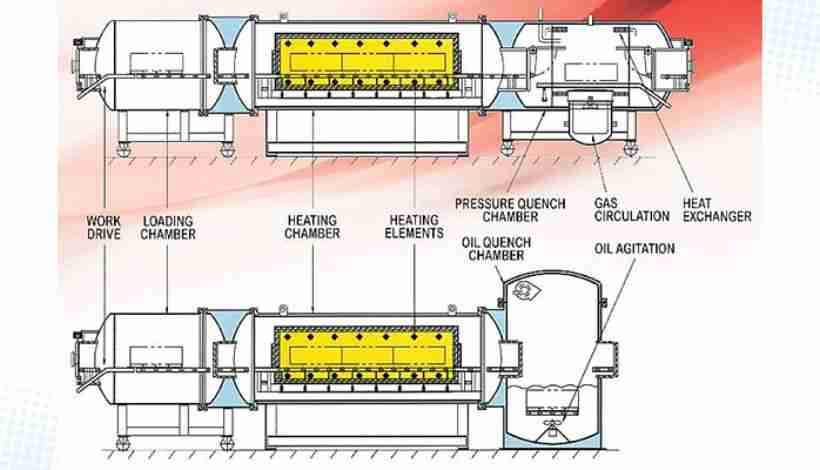
High-temperature sintering furnace with parts undergoing densification - where most MIM failures begin if temperature control is compromised
A medical device manufacturer experienced costly failures when their Ti-6Al-4V parts failed fatigue testing.The root cause? Sintering at the wrong temperature for Ti-6Al-4V.
Defect-free sintering is process control, not luck — our custom MIM parts production runs CMM-verified with documented furnace profiles.
💀 The Silent Killer: Sintering Failure
Every part looked perfect. Dimensions were spot on. Visuals passed.
But they failed catastrophically under load.
Why? Because Most MIM failures originate in the furnace. Here is your guide to stopping them.
The 7 Deadly Failure Modes
Understanding this taxonomy is step one. Every failed part traces back to these.
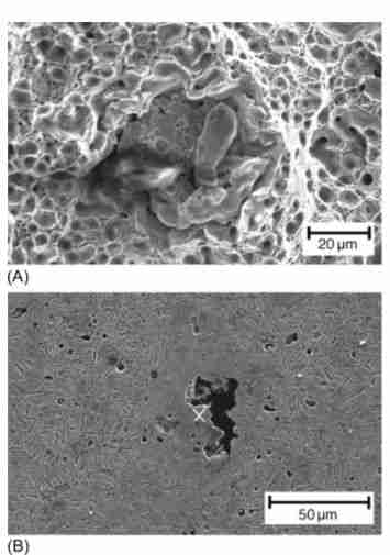
✅ Success Criteria: The Non-Negotiable Targets
- ☑️Density:96-99% Theoretical
- ☑️Temp Uniformity:±3-5°C Max
- ☑️Carbon:±0.05% of target
- ☑️Oxygen:<500 ppm (Steel)
- ☑️Geometry:±0.3% Accuracy
- ☑️Microstructure:Equiaxed grains
Miss ONE of these, and the part fails.
The Metallurgical Foundation
You start with a "Brown Part" that is 40% air and has zero strength. Here is how the furnace transforms it.
1. Binder Removal (300-600°C)
Goal:Vapor escapes without pressure build-up.
2. Densification (>1200°C)
Goal:40% void space shrinks to <4%.
3. Microstructure Control
Goal:Optimal grain size & phase balance.
📏 The Shrinkage Reality
Linear Shrinkage:15-22% |Volume Reduction:40-50%
Because the part shrinks so much, any non-uniformity in temperature or section thickness creates massive internal stress → Warping.
Video: Professional MIM sintering workflow. Source: OptiMIM
Failure Mode 1: Geometric Distortion (Warping)
📊 The Stats:
- Frequency:15-25% of all failures
- Detection:Visual / CMM
- Severity:High (Scrap)
1. How to Recognize It
👀 Visual Symptoms:
- Bent or Twisted parts.
- Sagging horizontal surfaces.
- Mating failures (Won't assemble).
📏 Measurement Signs:
- Deviation >±0.5% (Beyond shrinkage tolerance).
- Flatness issues.
- Non-parallel surfaces.
2. The Mechanism: Differential Shrinkage
Parts distort when different regions shrink at different rates. TheCritical Zoneis 300-600°C (Binder Decomposition).
3. Root Causes & Fixes
🔥 Root Cause 1: Temperature Non-Uniformity
Hot spots shrink faster; cold spots shrink slower. Result: Bending.
>±10°C:Failure
📐 Root Cause 2: Design Issues
Thin Walls (<0.5mm):Sag under gravity.
Asymmetry:Unbalanced shrinkage forces.
🧱 Root Cause 3: Poor Fixturing
No Setters:Friction causes drag.
Fix:Use contoured ceramic setters or powder beds to allow free shrinkage.
⚗️ Root Cause 4: Green Density Variation
Dense spots shrink less; porous spots shrink more.
Fix:Optimize Injection Molding upstream.
✅ Prevention Strategy Checklist
- ☑️Verify Temp:Monthly survey for ±5°C uniformity.
- ☑️Support:Use custom setters for complex shapes.
- ☑️Design:Keep wall thickness uniform (±20% max).
- ☑️Load:Don't block gas flow in the furnace.
Failure Mode 2: Cracking & Blistering
📊 The Stats:
- Frequency:10-15% of all failures
- Detection:Visual / Dye Penetrant
- Severity:Total Scrap (Unrepairable)
1. How to Recognize It
⚡ Cracking Signs:
- Surface/Internal fractures.
- Corner cracks (Stress concentration).
- Fine "Debind" crack network.
🎈 Blistering Signs:
- Raised bubbles (1-10mm).
- Pitted surface.
- Internal voids in thick sections.
2. The Mechanism: Stress > Strength
EitherThermal ShockorGas Pressureexceeds the part's weak green strength.
| Mechanism | Description | Critical Heating Rate |
|---|---|---|
| Thermal Shock | Surface expands faster than core. | Safe: 2-5°C/min |
| Gas Pressure | Binder turns to vapor faster than it escapes. | Marginal: 5-8°C/min |
| Constraint | Shrinkage blocked by friction. | Danger: >8°C/min |
3. Root Causes & Fixes
🔥 Root Cause 1: Excessive Heating Rate
Rushing the cycle kills the part.
🧼 Root Cause 2: Incomplete Debinding
Residual binder creates pressure bomb during sintering.
📐 Root Cause 3: Sharp Corners
Stress concentrators initiate cracks.
✅ Prevention Strategy Checklist
- ☑️Ramp Control:2-3°C/min in 300-600°C range.
- ☑️Debind Check:Target 95-98% removal.
- ☑️Design:No sharp internal corners.
- ☑️Cooling:Staged cooling to prevent thermal shock.
Failure Mode 3: High Residual Porosity (The Silent Killer)
📊 The Stats:
- Frequency:30-40% of failures (Most Common)
- Detection:Density / CT / Metallography
- Severity:High (Fatigue Failure in Field)
1. How to Recognize It
Direct measurements are the only way. Visual inspection is useless.
⚖️ Archimedes Density
Marginal:94-96%
Fail:<94%
🎈 Helium Pycnometry
Critical for HIP:Must verify >92% closed porosity.
🔬 Metallography
2. The 3 Failure Mechanisms
🔥 1. Insufficient Thermal Energy (Under-sintering)
Temp too low or Time too short. Atomic diffusion is exponential; 20°C drop = 50% slower rate.
🛡️ 2. Surface Contamination (Oxides)
Oxide layers block atoms from touching. Even if temp is perfect, bonding cannot happen.Solution:Reducing atmosphere (H₂).
🎈 3. Trapped Gas (The HIP Killer)
Pores close at 92% density. If gas is trapped inside, pressure builds and stops shrinkage.Solution:Vacuum sintering.
3. Root Causes & Troubleshooting
| Root Cause | Process Failure | The Fix |
|---|---|---|
| Temp Control | Thermocouple drift, loading too heavy. | Calibrate quarterly. Map uniformity. |
| Hold Time | Thick sections under-sintered in core. | Double hold time for >10mm parts. |
| Atmosphere | O₂ >10ppm, Dewpoint >-40°C. | Install O₂ analyzers. Fix leaks. |
| Carbon Residue | Binder residue blocks diffusion. | Extend debinding time/temp. |
✅ Prevention Strategy Checklist
- ☑️Calibration:Quarterly thermocouple checks.
- ☑️Monitoring:Continuous O₂ (<10ppm) & Dewpoint (<-40°C).
- ☑️Verification:Archimedes density on every batch.
- ☑️HIP Rule:Never HIP parts <92% density.
Failure Mode 4: Uncontrolled Grain Growth (Over-Sintering)
📊 Failure Stats:
- Frequency:8-12% of failures
- Detection:Metallography (Grain Size)
- Severity:Fails Mechanical Specs (Hidden Defect)
The Paradox: near-full density, Poor Properties
Counterintuitive Failure:Parts pass dimensional and density checks (97-99%) but fail under load.
Why? The Hall-Petch Relationship:Yield strength is inversely proportional to the square root of grain size.
- Small Grains:More boundaries = More obstacles to dislocation =High Strength
- Large Grains:Fewer boundaries = Easier dislocation motion =Low Strength/Toughness
1. How to Recognize It
🔬 Metallographic Signatures
- Grain size exceeds spec (2-3x target).
- Very few grains per unit area.
- Structure appears "Coarse" vs "Fine".
🔨 Mechanical Signatures
- Hardness:Lower than expected.
- Tensile:Below specification.
- Impact:Brittle behavior (Charpy).
- Fatigue:Reduced life.
2. The Mechanism: Thermodynamics & Kinetics
The Driver:The system minimizes energy by reducing grain boundary area (small grains consumed by large ones).
🌡️ Temp Sensitivity
- 20°C overshoot → Grain size doubles.
- Doubled size → 10-15% Strength loss.
⏱️ Time Sensitivity
- Hour 1:Densification dominates.
- Hour 3+:Grain growth dominates.
3. Root Causes & Process Failures
✅ Prevention Strategy Checklist
- 🌡️ Temperature:
- ☑️ Find minimum temp via DOE.
- ☑️ Calibrate thermocouples monthly.
- ⏱️ Time:
- ☑️ Use minimum hold time (No safety margins).
- ☑️ Extend time only for thick sections.
- ❄️ Cooling:
- ☑️ Fast cool to 1000°C.
- 🔬 Verification:
- ☑️ Periodic ASTM E112 Grain Size check.
- ☑️Pro Tip:Use Sinter + HIP for 99.9% density + fine grains.
Failure Mode 5: Phase Instability (The Hidden Defect)
📊 The Silent Threat:
- Frequency:12-18% of failures
- Detection:Magnetic / Corrosion / XRD
- Severity:Catastrophic Field Failure (No Visual Signs)
Why It's Dangerous
Zero Visual Indication:Parts pass dimensional and density checks perfectly.
Real World Consequence:A "stainless" steel part rusts immediately, or a non-magnetic part triggers a sensor.
1. The Mechanisms: Chemistry Gone Wrong
Two main ways this happens:Wrong Atmosphere(Chemistry shift) orWrong Cooling(Bad precipitates).
🧪 Case A: Nitrogen Steels (e.g., Nitronic)
The Failure:Sintered in Vacuum → Nitrogen/Manganese evaporates.
Result:Loss of austenite stabilizers → Turns into Magnetic Ferrite.
🧪 Case B: 17-4PH Stainless
The Failure:Sintered in Nitrogen → N absorbs → Reacts with Cr.
Result:Forms Cr₂N precipitates → Intergranular Corrosion & No Hardening.
2. Root Causes & Process Failures
🔥 Root Cause 1: Material-Atmosphere Mismatch
There is no "universal atmosphere." Check this matrix:
| Material | ✅ Acceptable | ⚠️ Caution | ❌ FORBIDDEN |
|---|---|---|---|
| 316L SS | H₂, Vacuum, Ar | Nitrogen (>0.4% reduces ductility) | - |
| 17-4PH | H₂, Vacuum | Argon (Verify purity) | NITROGEN (Catastrophic) |
| Nitrogen Steels | Controlled N₂ | Vacuum (Evaporation risk) | Hydrogen (Decarburization risk) |
| Titanium | High Vac (<10⁻⁵), Pure Ar | Std Vacuum (<10⁻⁴) | Oxygen (Any) |
❄️ Root Cause 2: Insufficient Cooling Rate
Slow cooling allows bad phases (like Chromium Nitride) to form. You must race through the danger zone.
The Critical Threshold (1000°C → 700°C):
✅ Prevention Strategy Checklist
- 🛡️ Atmosphere:
- ☑️ Enforce material-specific gas rules (No N₂ for 17-4PH!).
- ☑️ Install real-time monitoring (O₂, Dewpoint).
- ❄️ Cooling:
- ☑️ Target >150°C/min for nitrogen steels.
- ☑️ Install Gas Quench capability if needed.
- 🔍 Verification:
- ☑️ Magnetic Permeability check (for non-mag alloys).
- ☑️ Intergranular Corrosion Test (ASTM A262).
- ☑️ Carbon/Nitrogen content analysis.
Failure Mode 6: Carbon Contamination (The Hardness Killer)
📊 The Hardness Trap:
- Frequency:8-12% of failures
- Detection:Hardness / Carbon Analysis
- Severity:High (Wear Resistance Failures)
The Tightrope Walk
Carbon determines hardness. The window is incredibly narrow (e.g., Tool Steel ±0.05% C).
📈 Carburization (Too Much C)
Result:Brittle carbide networks, low melting point eutectics (distortion).
Source:Residual binder, oily furnace.
📉 Decarburization (Too Little C)
Result:Soft surface, poor wear resistance.
Source:Wet Hydrogen (High Dew Point), Oxygen leaks.
1. The Mechanisms: Chemistry at Work
Mechanism A: Binder Residue (Carburization)
If binder doesn't decompose cleanly, carbon dumps into the steel.
The Chain Reaction:
- Incomplete Debinding → 2. Backbone Binder remains → 3. Decomposes at Sinter Temp → 4. Carbon dissolves into matrix.
Mechanism B: Wet Atmosphere (Decarburization)
Moisture is the enemy. It strips carbon from the surface.
The Reaction:H₂O + C (in steel) → CO + H₂
Result: Carbon leaves the steel as gas.
Critical Dew Point:Must be < -40°C. If > -20°C, significant carbon loss occurs.
2. Root Causes & Process Failures
🔥 Root Cause 1: Incomplete Debinding
Rushing the debind cycle leaves "fuel" for carburization.
💧 Root Cause 2: Wet Hydrogen
Wet gas acts as a carbon sponge.
🏭 Root Cause 3: Dirty Furnace
Binder residue or oil/grease on parts creates a carbon-rich environment.
✅ Prevention Strategy Checklist
- 🧪 Analysis:
- ☑️ Measure Weight Loss (Every batch).
- ☑️ Carbon Analysis of sintered parts (Target ±0.05%).
- 🛡️ Atmosphere:
- ☑️ Monitor Dew Point (<-40°C).
- ☑️ Check for leaks/Oxygen ingress.
- 🧼 Hygiene:
- ☑️ Clean furnace binder traps.
- ☑️ Ensure parts are oil-free.
Failure Mode 7: Oxidation Embrittlement (The Titanium Killer)
📊 The Titanium Threat:
- Frequency:>50% of Titanium failures
- Detection:Oxygen Analysis / Ductility Loss
- Severity:Total Scrap (Irreversible)
Why It's Deadly for Reactive Metals
Unlike Rust:Oxygen doesn't just sit on the surface. It dissolves into the crystal lattice.
The Result:500ppm Oxygen makes Titanium as brittle as glass.It cannot be removed.
1. The Mechanisms: Surface vs. Lattice
🛡️ Mechanism 1: Surface Oxide (All Metals)
- Metal + O₂ → Oxide Layer.
- Blocks diffusion bonding (High Porosity).
- Fixable:H₂ atmosphere can reduce oxides (FeO + H₂ → Fe + H₂O).
💀 Mechanism 2: Interstitial Dissolution (Titanium)
- Oxygen dissolvesintothe lattice.
- Increases hardness/strength, butDuctility Plummets.
- Unfixable:Once dissolved, it stays forever.
2. Root Causes & Process Failures
🌌 Root Cause 1: Inadequate Vacuum
Different metals need different vacuum levels. Know your target:
🚪 Furnace Leaks
Door seals, thermocouples. Use Helium Leak Detection.
💨 Dirty Gas
Argon must be >99.999% purity. Dew point <-60°C.
🧪 Bad Powder
If starting powder has high oxygen, sintering cannot fix it.
✅ Prevention Strategy Checklist
For Stainless Steel (Moderate)
- ☑️ Vacuum: 10⁻⁴ mbar.
- ☑️ Dew Point: <-40°C.
- ☑️ Oxygen: <10 ppm.
- ☑️Benefit:H₂ actively removes oxides.
For Titanium (Extreme)
- ☑️Vacuum:10⁻⁵ to 10⁻⁶ mbar (Essential).
- ☑️Argon:Ultra-High Purity (Grade 5.0).
- ☑️Leak Test:Weekly.
- ☑️Powder:<1000 ppm Oxygen spec.
- ☑️Getter:Use Erbium/Yttrium scavengers.
Equipment Control Capabilities: What Your Furnace Must Have
Your furnace is a precision metallurgical reactor. To stop the 7 failure modes, it needs these 6 capabilities.
Example: The 10-Stage 316L Profile
A "single ramp" kills parts. You need a complex recipe like this:
Failure Correlation Matrix
| Missing Capability | Direct Consequence | Resulting Failure Mode |
|---|---|---|
| Multi-Zone Control | Temp Gradients (>10°C) | #1 Distortion, #4 Over-Sintering |
| Atmosphere Control | Oxygen/Dewpoint Spikes | #7 Oxidation, #6 Carbon Contam. |
| Programmable Profile | Fast Heating in Burnout | #2 Cracking, #3 Porosity |
| Active Cooling | Slow Cool (<50°C/min) | #5 Phase Instability (Precipitation) |
Diagnostic Checklist: Identify Your Failure Mode
Use this logic flow to pinpoint the exact failure. Start at Step 1.
Step 4: Specialized Cases
- 🧲 Magnetic (when should be non-mag):Failure Mode 5 (Phase Instability).
- 🧪 Corrosion Failure:Failure Mode 5 (Intergranular attack).
- 🛡️ Won't Harden (17-4PH):Failure Mode 5 (Nitrogen contamination).
Step 5: Root Cause Investigation
You identified the mode. Now check these specific variables.
Mode 1: Distortion
- Temp uniformity ±5°C?
- Ramp 300-600°C <5°C/min?
- Part support adequate?
- Green density uniform?
Mode 2: Cracking
- Heating rate too fast?
- Debind weight loss >95%?
- Cooling shock?
- Sharp design corners?
Mode 3: High Porosity
- Peak temp reached?
- Hold time adequate?
- Atmosphere leaks (O₂)?
- Carbon residue?
Mode 4: Grain Growth
- Temp 10-20°C too high?
- Hold time too long?
- Cooling too slow?
Mode 5: Phase Stability
- Correct Atmosphere?
- Cooling rate fast enough?
- Vacuum evaporation?
Mode 6/7: Chemistry
- Dew point <-40°C?
- Vacuum leak tight?
- Gas purity spec?
- Powder O₂ content?
Video: The dramatic 20% shrinkage transformation. Source: CX MIM
Prevention Strategy: Joining the Elite 5%
Success isn't luck. It's a systematic approach across six pillars.
1. Process Control Excellence
- Temp:±3-5°C Uniformity Target.
- Ramp:Slow (2-5°C/min) in burnout zone.
- Hold:Validated via DOE.
- Cool:Fast (>150°C/min) for Nitrogen steels.
2. Atmosphere Excellence
- Purity:Gas Grade 5.0 (99.999%).
- Monitoring:O₂ <10ppm, Dewpoint <-40°C.
- Vacuum:10⁻⁵ mbar for Ti.
- Rules:Strict material-gas matching.
3. Maintenance Excellence
Weekly:Leak Rate + O₂ Zero Check.
Monthly:Thermocouple verification.
Quarterly:Full TUS & Calibration.
4. Quality Verification
- Brown:95-98% weight loss check.
- Sintered:Density (96-99%) & Visual.
- Periodic:Metrology, Chemistry, Hardness.
- HIP:Helium Pycnometry (>92% closed).
5. Data-Driven Excellence
- Logging:All sensors, every 10s.
- SPC:Control charts for Peak Temp & Vacuum.
- Traceability:Part ID linked to Thermal Profile.
6. Organizational Excellence
- Training:Metallurgy & Failure Modes.
- Design:Wall thickness ±20% max.
- Mindset:Furnace is an instrument, not an oven.
📅 The Maintenance Calendar
Prevent drift before it kills parts.
🔍 The Quality Verification Gate
Dimens. & Weight Check
95-98% Weight Loss
Density (96%) & Hardness
Frequently Asked Questions
Q: How do I know if my temperature is correct?
96-99% Density + Correct Grain Size + Correct Phase. For Low Density (<95%), the cause is typically temperature too low or time too short; fix this by adding 10-20°C or 20-50% time. For Large Grains, the cause is temperature too high or time too long; fix this by reducing 10-20°C or reducing time. Starting Points (Reference): 316L at 1320°C, 17-4PH at 1340°C, Ti-64 at 1350°C, and M2 Tool Steel at 1260°C (±10°C Window!).
Q: My parts keep warping. Root cause?
Follow this diagnostic flow: 1) Check Temp Uniformity: Is variation >±5°C? If yes, fix the furnace. 2) Check Ramp Rate: Is 300-600°C rate >5°C/min? If yes, slow down to 2-3°C/min. 3) Check Green Uniformity: Density variation >3%? Fix injection molding. 4) Check Support: Are unsupported spans sagging? Use contoured setters.
Q: Minimum equipment needed?
Non-Negotiable Essentials include Multi-zone Control (minimum 3 zones), Programmable Profile (minimum 20 segments), Atmosphere (Vacuum 10⁻⁴ mbar or High Purity Gas), and Data Logging (for traceability). High ROI Add-ons include Real-time Monitoring (Oxygen & Dewpoint analyzers), Controlled Cooling (Gas Quench, which is essential for hardening), and Ultra-High Vacuum (10⁻⁶ mbar, which is mandatory for Titanium).
Q: Preventing 17-4PH Magnetism/Corrosion?
Beware of the Nitrogen Trap. If you sinter 17-4PH in Nitrogen, the nitrogen absorbs and reacts with chromium to form Cr₂N precipitates. This results in intergranular corrosion and stabilized austenite (the part becomes non-magnetic/soft). The strict rule is to use Hydrogen or Vacuum ONLY. NEVER use Nitrogen or Forming Gas.
Q: Real-world consequence of porosity?
"Looks fine" is dangerous because porosity kills fatigue strength. For example, 95% density (5% porosity) yields 75-80% tensile strength and a risky 60-70% fatigue strength. 98% density (2% porosity) yields 90-95% tensile strength and 80-85% fatigue strength. Achieving 99.9% density via HIP (<0.1% porosity) provides 100%+ tensile strength and ~95% fatigue strength.
Q: Good vacuum, but parts still oxidize?
Vacuum level isn't just a number; it must match the material. Possible Cause 1: Inadequate Vacuum Level. 10⁻³ mbar is useless for most MIM, 10⁻⁴ mbar is OK for Steel, and 10⁻⁵ mbar is mandatory for Titanium. Possible Cause 2: Outgassing. Parts/setters release moisture. Fix this with a pre-bake or extended pump-down. Possible Cause 3: Powder Contamination. If the powder already has oxide, sintering won't fix it. Fix this by checking powder specifications.
Q: Can I use the same cycle for 316L and 17-4PH?
ABSOLUTELY NOT. 316L (Austenitic) can use Hydrogen, Vacuum, or Nitrogen atmospheres, is sintered at 1320°C, and requires moderate cooling (50°C/min). 17-4PH (Martensitic) must NEVER use Nitrogen, is sintered at 1340°C, and requires fast cooling (>100°C/min). Mixing cycles will result in corrosion failure and soft parts.
Q: How tight should temp control be?
General Rule: ±5°C is the threshold between success and failure. ±10°C is forgiving and acceptable for Low-Alloy Steels and Bronze. ±5°C is the standard for 316L, 17-4PH, and Titanium. ±3°C is critical and required for Tool Steels (M2) and Super-alloys.
Q: Can failed MIM parts be reworked after sintering?
A: No. Sintering defects — cracking, blistering, warpage, distortion — are irreversible: the part cannot be re-sintered flat or welded back to spec economically. That is exactly why defect prevention concentrates upstream in debinding ramps and green-part handling rather than downstream repair.
Q: How do you prevent sintering distortion?
A: The main levers are uniform wall thickness in the design, correct part support and setter geometry in the furnace, and a debinding window slow enough to avoid internal stress. Distortion mechanisms and their prevention pair naturally with the geometry limits on the size limitations page.
Q: Do MIM parts fail suddenly without warning?
A: Fatigue cracks in MIM parts initiate at stress concentrators — pores, notches, section changes — and grow progressively under cyclic load, so failures are not random. Within design stress and a validated process window, parts hold; the general property trade-offs are on the advantages and disadvantages page.
Conclusion: The Path from 95% Failure to Consistent Success
Sintering is where MIM parts are born or die. Loss of control over justoneparameter triggers a cascade of failures.
🎛️ The 7 Variables That Determine Success
1. Temp Uniformity
2. Heating Rate
3. Peak Temp/Time
4. Atmosphere
5. Cooling Rate
6. Density Goal
7. Microstructure
🏆 What the Elite 5% Do Differently
- ★Process Discipline:Documented protocols, strictly enforced.
- ★Equipment Investment:Paying for precision control capability.
- ★Verification Rigor:Testing at every stage. SPC to detect drift.
- ★Data-Driven:Full traceability and root cause analysis.
- ★Organizational Expertise:Continuous learning culture.
🗺️ Your Path Forward
💰 The Economic Reality
The cost of proper control (equipment, monitoring) isinsignificantcompared to the cost of failure (scrap, recalls, lost reputation).
Final Thought
Sintering is precision metallurgical engineering requiring simultaneous control of seven interdependent variables. Master this, and you transform fragile powder into high-performance components. Neglect it, and you remain in the 95% who struggle.
Join the elite 5%. Your parts—and your customers—depend on it.
Precision Metal Parts from Emitech
Nanjing Emitech delivers MIM, CNC machining, and custom metal parts. MIM services · Request a quote
Last updated: 2026-07-23
Continue reading
- Small Gear Materials Selection: Complete Guide to Steel, Aluminum & Advanced Composites
- What Are MIM Parts? A Complete Technical Guide to Metal Injection Molding
- What is Metal Injection Molding (MIM) for Aluminum? Benefits and Applications Explained
- Comprehensive Guide to the Yield Strength of 316 Stainless Steel