
What Are MIM Parts? Definition & Process
Quick Answer
MIM parts are small, complex metal components (typically 0.1–240 g) made by metal injection molding — powder plus binder, molded, debound, and sintered to near-full density. For industrial programs (medical, automotive, electronics), source parts through custom MIM parts and MIM manufacturing services, not firearm forum articles.
Next step: Request a quote with STEP/PDF drawings, material, volume, and tolerances.
Quick Answers to Top MIM Questions
How much do MIM parts cost?
Per-part price depends on material, complexity, and volume — send your drawing for a firm quote (plus a one-time tooling investment)
What's the minimum order quantity?
1,000-5,000 parts for low-volume production; 10,000+ for cost-optimized high-volume runs
How long does MIM manufacturing take?
8-14 weeks for first article samples; 4-8 weeks for repeat production orders
What materials work with MIM?
Stainless steel (316L, 17-4PH), titanium alloys, tungsten, soft magnetic Fe-Ni, and copper alloys
What tolerances can MIM achieve?
±0.3-0.5% as-sintered; ±0.05-0.1mm with secondary sizing operations
What Are MIM Parts? Definition and Technical Overview
MIM parts are precision metal components manufactured through Metal Injection Molding—a net-shape process that produces geometrically complex parts from fine metal powders. The process binds metal powder (typically 85-97% of total volume) with thermoplastic and wax binders, which are later removed before sintering.
When You Should Consider MIM
You should evaluate MIM technology when your application requires:
- Part weights between 0.1 to 240 grams
- Dimensional tolerances of ±0.3% to ±0.5%
- Production quantities exceeding 5,000-10,000 units annually
- Complex features requiring multiple CNC setups or investment casting
Quick Decision Framework
Choose MIM if:
- ✓ Annual volume > 10,000 units
- ✓ Part has ≥3 complex features
- ✓ Tolerances ±0.3-0.5% acceptable
- ✓ Multiple wall thicknesses needed
Stick with CNC if:
- ✗ Prototype quantities (<500 units)
- ✗ Need ±0.05mm tolerances everywhere
- ✗ Sharp internal corners required
- ✗ Part weight >300 grams
Technical Distinction from Other Processes
Unlike PM (Press & Sinter):MIM uses feedstock injection rather than die compaction, enabling three-dimensional complexity impossible with uniaxial pressing.
Unlike Investment Casting:MIM achieves 95-99% theoretical density with minimal porosity and tighter dimensional control (±0.3% vs. ±1-2%).
Unlike CNC Machining:MIM produces net-shape parts without material waste, eliminating 5-15 machining operations for complex geometries.
The technology originated in the 1970s and has matured into a significant global industry serving medical devices, automotive sensors, consumer electronics, and firearms components.
How MIM Parts Are Made: Step-by-Step Manufacturing Process
Understanding the four-stage MIM process helps you optimize designs and set realistic expectations for lead times and tolerances.
Stage 1: Feedstock Preparation
The feedstock consists of metal powder (particle size 2-20 microns) mixed with polymer binders at carefully controlled ratios. Common binder systems include paraffin wax + polypropylene, polyacetal-based binders, and water-soluble binders.
Material mixing ratios:
- Metal powder: 85-97% by volume
- Polymer binder: 3-15% by volume
- Powder particle size: 2-20 microns (finer = better surface finish)
Stage 2: Injection Molding
Standard plastic injection molding machines inject feedstock into tool steel molds at temperatures of 150-200°C and pressures of 500-1,500 bar. This produces "green parts" with the same geometry as your final component, but 15-20% larger to account for sintering shrinkage.
COMMON MISTAKE:Specifying features smaller than 0.5mm radius. MIM cannot replicate sharp corners due to powder flow limitations during injection. Always design with minimum 0.5mm radii.
Stage 3: Debinding (Binder Removal)
Debinding removes 90-95% of the binder system while maintaining green part integrity through two phases:
Primary debinding:4-48 hours (produces "brown parts" with open pore structure)
Secondary debinding:400-600°C thermal removal of remaining binder
You should expect 0.5-2% dimensional change during debinding, primarily in the thickness direction.
Stage 4: Sintering (Final Densification)
Sintering bonds metal particles through solid-state diffusion at 1,120-1,450°C in controlled atmospheres:
| Material | Atmosphere | Temperature |
|---|---|---|
| Stainless steel 316L | Hydrogen or vacuum | 1,350-1,400°C |
| Titanium Ti-6Al-4V | Argon or high vacuum | 1,260-1,350°C |
| Fe-2Ni | Dissociated ammonia | 1,120-1,150°C |
During sintering, your part shrinks 15-20% linear shrinkage (38-49% volumetrically) and achieves 95-99% theoretical density. Total cycle time ranges from 8-36 hours.
KEY TAKEAWAY:
Sintering shrinkage (15-20%) is THE most critical dimension control factor. If your supplier can't show Cpk ≥1.33 data on shrinkage consistency, look elsewhere.
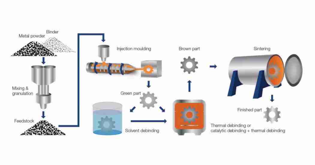
The four critical stages of MIM production from powder to finished part
Post-Sintering Operations
Standard secondary operations you may require:
- Steam treatment:Enhances corrosion resistance of stainless steel
- Sizing/coining:Tightens tolerances to ±0.1% on critical features
- Heat treatment:Hardening (17-4PH to H900), stress relief
- Surface finishing:Tumbling, grinding, polishing to Ra 0.2-0.4 μm
Watch: Complete MIM Manufacturing Process
This professional video from the Metal Powder Industries Federation (MPIF) demonstrates actual factory floor operations including injection molding, debinding, and sintering processes.
MIM Parts vs CNC Machining vs Casting: Cost Comparison
The cost-effectiveness of MIM depends on three factors: part complexity, production volume, and material utilization.
Economic Crossover Analysis
| Manufacturing Method | Setup Cost | Per-Unit Cost (100K) | Material Efficiency |
|---|---|---|---|
| MIM | High | Low | 95-97% |
| CNC Machining | None | High | 30-60% |
| Investment Casting | Medium | Medium | 60-80% |
When to Choose Each Method
You should choose MIM when:
- Annual volume exceeds 10,000 units (breaks even vs. CNC)
- Part has 3+ features requiring multiple CNC setups
- Material cost represents >40% of machined part cost
- Tolerances of ±0.3-0.5% are acceptable
CNC remains superior for:
- Prototype quantities (<500 units)
- Tolerances tighter than ±0.1mm required on all features
- Parts with sharp internal corners (MIM requires 0.5mm minimum radii)
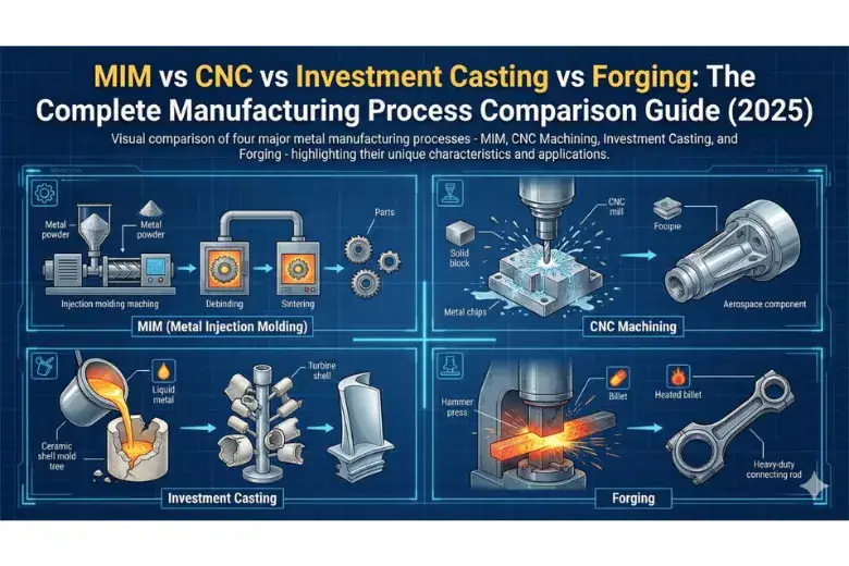
MIM breaks even at 10K units vs CNC and 50K vs casting for complex geometries
Real-World Cost Example
For a high-volume automotive sensor housing in 316L stainless steel, MIM typically eliminates the majority of CNC machining time and material waste, resulting in substantial annual savings once tooling is amortized.
Common Materials Used in MIM Parts Production
Stainless Steel Alloys (50-60% of MIM Market)
316L: Your default choice for corrosion resistance
- Properties: 170-200 HV hardness, 520-580 MPa tensile strength
- Applications: Surgical instruments, watch cases, food processing
- Cost: commodity MIM stainless powder
17-4 PH: When you need precipitation hardening
- Heat-treated (H900): 40-44 HRC, 1,100-1,300 MPa tensile strength
- Applications: Aerospace fasteners, valve components, firearms parts
- Cost: commodity MIM stainless powder
420 / 440C: For wear resistance and cutting edges
- Heat-treated hardness: 50-58 HRC
- Applications: Surgical blades, lock components, cutting nozzles
Iron and Low-Alloy Steels
Fe-2Ni: Your economical option
- Cost: the lowest-cost MIM material
- Applications: Automotive sensors, power tool gears, industrial fasteners
Fe-8Ni: When dimensional precision is critical
- Near-zero shrinkage variation (±0.1%)
- Applications: Optical component mounts, precision housings
Titanium Alloys
Ti-6Al-4V: Aerospace and medical grade
- Strength-to-weight: 25-30 MPa/(kg/m³)
- Biocompatibility: ASTM F136/F3001 compliant
- Cost: premium-priced powder (restricts use to high-value applications)
- Applications: Dental implants, aerospace brackets, surgical instruments
Material Selection Cheatsheet
🔧 QUICK MATERIAL SELECTOR:
- Need corrosion resistance?→ 316L stainless
- Need hardening capability?→ 17-4PH stainless
- Budget-conscious structural?→ Fe-2Ni
- Biocompatible implant?→ Ti-6Al-4V or 316L
- Extreme density required?→ Tungsten heavy alloy
- Magnetic properties needed?→ Fe-Ni soft magnetic
- Wear resistance priority?→ 440C or carburized Fe-2Ni
REAL-WORLD INSIGHT:
A typical smartphone hinge contains 8-12 MIM parts weighing less than 2 grams each. Every part must survive 200,000+ folding cycles. Apple, Samsung, and Xiaomi specify MIM over CNC for these components—the cost savings at high volumes can be substantial.
Industries That Use MIM Parts
[caption id="attachment_15052" align="alignleft" width="500"]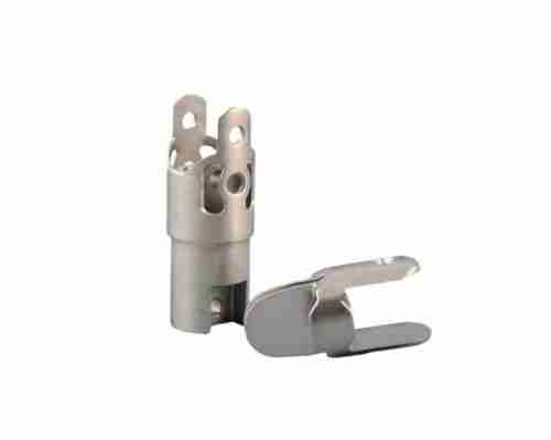 MIM produces complex geometries across medical devices, automotive, and consumer electronics[/caption]
MIM Parts for Medical Devices
Common applications:
- Orthodontic brackets: 316L or 17-4PH, 0.3-1.5g per piece
- Surgical instruments: Biopsy forceps, laparoscopic joints
- Implantable devices: Spinal fusion cages, dental implant abutments
Quality requirements:
- ISO 13485 quality management certification (mandatory)
- Material certifications per ASTM F899 (316L) or F2885 (17-4PH)
- Biocompatibility testing per ISO 10993 series
- Full traceability to raw material lot level
Automotive Applications
Common MIM components:
- Turbo VGT vanes: 17-4PH, 3-6g, 6-12 parts per vehicle
- ABS sensor housings: 316L, 8-15g
- Transmission pawls: Fe-2Ni, 5-12g
- Seat belt pretensioners: High-strength steel, 10-25g
Requirements:Documented quality management system mandatory (18-24 month qualification timeline)
Consumer Electronics
Typical applications:
- Smartphone hinge mechanisms: 0.5-1.5g parts, ±0.05mm tolerances
- Camera lens barrel threads: 17-4PH for wear resistance
- SIM card trays: Precision ejection mechanisms
Volume expectations:100,000-5,000,000 units annually
Firearms and Defense
Common components:
- Pistol trigger assemblies, magazine components, safety mechanisms
- Material: 17-4PH heat-treated to H900 condition (38-42 HRC)
- Note:Properly manufactured MIM components meet or exceed investment cast parts in fatigue life per SAAMI testing
How to Find Reliable MIM Parts Manufacturers
Minimum Supplier Qualifications
✓Documented quality management system(site-specific, not just corporate)
✓Cpk ≥1.33 datafor dimensional control on similar parts
✓3+ customer referencesin your target industry
✓In-house tooling capability(design and maintenance)
✓Process documentation(injection, debinding, sintering profiles)
Industry-Specific Certifications
| Industry | Required Certifications |
|---|---|
| Medical Devices | ISO 13485 + ASTM F899 |
| Automotive | Documented inspection plans + Cpk data |
| Aerospace | NADCAP special processes + traceability |
| Defense/Firearms | Material certificates + ITAR |
Red Flags That Should Disqualify Suppliers
❌ Cannot provide material certifications with lot traceability
❌ Refuses to share Cpk data or claims "we inspect 100%"
❌ Pricing 50%+ below market rate (cutting corners)
❌ No documented first article inspection procedure
❌ Won't provide customer references in your industry
Geographic Considerations
North America:+30% cost, better IP protection, ITAR compliance
Asia (Taiwan, China):−40% cost, higher capacity, IP risks
Europe:+50% cost, ultra-precision (±0.05mm tolerances)
MIM Parts Pricing and Cost Factors
Cost Structure Breakdown
Tooling costs (one-time):quoted per project. The main cost drivers are:
- Cavity count (4-, 8-, or 16-cavity molds)
- Part complexity — sliders, lifters, threads
- Tool steel grade and required shot life
Material costs:feedstock is priced per kg — Fe-Ni alloys are the most economical, stainless grades mid-range, and titanium the most expensive.
Processing costs:injection + debinding + sintering, quoted per part
Tooling Amortization
| Volume | Tooling Cost per Part (Amortized) |
|---|---|
| 10,000 | Highest |
| 50,000 | Moderate |
| 100,000 | Low |
| 500,000 | Minimal |
Key insight:Tooling becomes negligible (<5% of part cost) beyond 250,000 units.
How to Get Accurate Quotes
Essential RFQ information:
- 3D CAD files (STEP format)
- 2D drawings with GD&T callouts
- Material specification (316L, 17-4PH, etc.)
- Annual volume forecast (Year 1, 2, 3)
- Tolerance requirements (critical vs. non-critical features)
- Surface finish requirements (Ra values)
- Secondary operations needed
Cost Optimization Strategies
Design modifications:
- Eliminate undercuts requiring slides: saves significant tooling cost
- Standardize wall thickness 0.8-2.0mm: Reduces scrap 10-15%
- Relax non-critical tolerances to ±0.3%: Saves 15-25% per part
Material substitution:
- Fe-2Ni instead of 316L: 60% material cost reduction (where corrosion resistance not critical)
- 17-4PH instead of 440C: 25% savings (when 50 HRC suffices)
Lead Times and Minimum Order Quantities
Typical Lead Times
Phase 1: Tooling fabrication→ 8-14 weeks
Phase 2: First article production→ 10-14 weeks from PO
Phase 3: Production runs→ 4-8 weeks repeat orders
Prototype Strategy
- CNC prototypes(Week 0-4): 10-25 units, quoted per part
- Soft tool samples(Week 6-10): 100-200 units, modest tooling cost
- Hard tool investment(Week 10-22): quoted per project
- Production release(Week 24+)
Never skip soft tooling for new designs.The modest soft-tooling investment prevents expensive hard-tool mistakes.
Minimum Order Quantities
| Production Stage | MOQ Range | Rationale |
|---|---|---|
| Prototype/NRE | 50-500 parts | Soft tooling validation |
| Low-volume | 1,000-5,000 parts | Minimum sintering batch |
| High-volume | 10,000-50,000 parts | Optimized furnace loading |
Industry expectations:
- Medical devices: 1,000-5,000
- Automotive: 10,000-50,000
- Consumer electronics: 50,000-500,000
Frequently Asked Questions
Q: What are MIM parts made of?
MIM parts start as a feedstock of fine metal powder (typically under 20 μm) mixed with a thermoplastic binder. After molding, the binder is removed and the part is sintered into solid metal. Common MIM materials include stainless steels (316L, 304, 17-4 PH), low-alloy steels (4605, 8620), titanium, tool steels, and copper alloys.
Q: Are MIM parts metal or plastic?
Metal. The plastic binder is only a processing aid — it is completely removed during debinding. The finished MIM part is 95–99% dense solid metal with mechanical properties close to wrought material, so it is strong enough for structural applications.
Q: What are MIM parts used for?
MIM parts appear wherever small, complex metal components are needed in volume: smartphone hinges and camera parts, surgical instruments, automotive sensors and turbocharger components, firearm fire-control parts, watch cases, and industrial hardware. See MIM parts by industry for examples.
Q: What are the advantages of MIM parts?
MIM combines the shape complexity of plastic injection molding with the properties of solid metal: net-shape production of intricate geometry by an experienced MIM manufacturer, 95–97% material utilization, excellent repeatability at volumes of 10,000+ per year, and per-part costs far below machining for complex shapes. Full list: MIM parts benefits.
Q: What are the limitations of MIM parts?
MIM suits parts of roughly 0.1–200 g (maximum dimension ~150 mm), requires tooling investment of $3,000–$15,000, and becomes economical mainly at annual volumes above 10,000 pieces. Very large parts, ultra-tight as-sintered tolerances, and low-volume runs are better served by machining — see MIM size limitations.
Q: How does shrinkage affect dimensions?
Sintering causes 15–20% linear shrinkage — the #1 dimensional control factor. Manufacturers compensate by scaling mold cavities 1.17–1.20× larger, holding furnace temperature within ±3–5°C, and running SPC monitoring with Cpk ≥1.33. Uniform wall thickness (±20% variation max) keeps shrinkage predictable.
Q: What surface finishes are achievable?
As-sintered surfaces run 1.5–3.0 μm Ra; tumbling reaches 0.8–1.2 μm Ra, grinding/polishing 0.2–0.4 μm Ra, and mirror polish below 0.1 μm Ra for surgical instruments. Coatings include PVD (TiN, CrN), electroplating, passivation, and black oxide — details on our surface treatment page.
Conclusion: Making the Right MIM Decision
Metal Injection Molding bridges the gap between CNC precision and casting economics for complex geometries at 10,000+ unit volumes.
Quick Decision Summary
Choose MIM when:
- ✓ Annual volume >10,000 units
- ✓ Part has ≥3 complex features
- ✓ Tolerances ±0.3-0.5% acceptable
- ✓ Material efficiency matters (95-97% vs. 30-60% CNC)
Choose alternatives when:
- ✗ Prototype quantities <500 units
- ✗ All dimensions need ±0.05mm tolerances
- ✗ Sharp internal corners mandatory
- ✗ Part weight >300 grams
ROI Reality Check
For a typical 10g part at 100,000 units:
- MIM total cost: quoted per project
- CNC total cost: quoted per project
- Annual savings: substantial at volume
Break-even:~8,500 units. Beyond 50K units, MIM isn't 20% cheaper—it's 70-85% cheaper than CNC.
Critical Success Factors
- Supplier qualification:Verify documented quality systems, Cpk ≥1.33, customer references
- Design optimization:Work with supplier early—DFM services reduce costs 20-40%
- Phased approach:Always prototype with soft tooling before committing to hard tooling
- Timeline realism:Budget 26-30 weeks for first production (not optimistic 16 weeks)
The investment in proper supplier qualification and design optimization pays back within the first 50,000-100,000 units through reduced per-part costs, improved quality, and eliminated secondary operations.
Ready to start?Prepare your RFQ with 3D CAD, tolerance requirements, and annual volume forecast—then evaluate 3-5 qualified suppliers against the criteria in this guide.
Source Custom MIM Parts from Emitech
Nanjing Emitech delivers MIM from tooling through sintering and finishing. Custom MIM parts · MIM services · Request a quote
Last updated: 2026-06-24
Continue reading
- Dimensional Tolerances in Metal Injection Molding: Design Best Practices & Analysis Methods
- Fe50Co Metal Injection Molding for Advanced Electronic Applications
- FeNi36 Alloy: Low Expansion Characteristics and Applications in Precision Instruments
- High-Precision Gears: Manufacturing Methods, Types, and Industrial Applications