
Important Note on Alloy Grades:This article covers both pure binary Fe50Co and vanadium-modified commercial grades (e.g., Hiperco 50, Vacoflux 50, containing ~1.5–2% V). Both deliver comparable magnetic performance, but V-modified grades offer significantly improved ductility and machinability. Engineers should distinguish between these grades when making manufacturing decisions.
Key Takeaways
- Unmatched Saturation:Delivers2.4 Teslaflux density, enabling 35–40% higher power density vs silicon steel.
- Thermal Stability:Maintains performance up to980°CCurie temperature, far exceeding ferrites and silicon steel.
- Cost & Material Efficiency:MIM eliminates>70% machining wasteand reduces tool wear, saving significant costs on expensive Fe50Co powder.
- Process Specifics:Requires precise50% powder loading (by volume)and>98% sintered densityto achieve optimal magnetic properties.
- Application Window:Ideal forDC to 10 kHzapplications; not recommended for frequencies above50 kHzdue to eddy current losses.
- Alloy Grade Distinction:Pure Fe50Co is extremely brittle and essentially unmachinable. V-modified grades (Hiperco 50, etc.) offer improved ductility, though MIM remains the preferred route for complex 3D geometries at production volumes.
You're trying to design miniature magnetic components with maximum power density, but traditional machining wastes 70% of your expensive Fe50Co material and destroys cutting tools within hours. Metal Injection Molding (MIM) eliminates this waste while producing complex geometries impossible to machine—finally making Fe50Co economically viable for high-volume electronic applications.
Why Fe50Co Delivers Unmatched Magnetic Performance
Fe50Co alloys deliver saturation magnetic induction up to2.4 Tesla—the highest of any commercially available soft magnetic material. In production MIM parts with optimized processing, you can reliably achieve:
| Property | MIM Fe50Co Value | Significance |
|---|---|---|
| Saturation Induction (Bs) | 2.0–2.3 T | 20–33% higher than silicon steel; 5–8× higher than ferrites |
| Maximum Permeability (μmax) | ~5,000–6,000 (up to 8,000+ after magnetic annealing) | Excellent sensitivity for sensors and actuators; as-sintered values are on the lower end without post-sinter annealing |
| Coercivity (Hc) | 1.5–2.0 Oe | Low hysteresis loss for efficient AC operation |
| Curie Temperature (Tc) | 980–1,100°C | Maintains full performance where other materials fail |
That Curie temperature is critical for your high-power-density electronics. While soft ferrites degrade above 250°C and silicon steel weakens beyond 770°C, Fe50Co maintains full magnetic performance in extreme thermal environments.
The Manufacturing Challenge
Here's the paradox: The ordered B2 crystal structure that gives Fe50Co its exceptional magnetic properties also makes itextremely brittle and difficult to machine.
Important distinction between alloy grades:
- Pure binary Fe50Co:Near-zero ductility, essentially unmachinable. Tool life measured in hours, reject rates extremely high.
- Vanadium-modified grades (Hiperco 50, Vacoflux 50 — ~1.5–2% V):Significantly improved elongation (10–15%), machining is feasible but still economically challenged at high volumes. For complex 3D geometries and production runs above ~10,000 units, MIM retains a decisive economic advantage even over V-modified grades.
What happens when you machine Fe50Co (either grade at scale):
- Carbide tools wear out in 2–4 hours (vs. weeks for stainless steel)
- Material waste exceeds60–70%in chip form
- Slow cutting speeds extend cycle times 5–20×
- High rejection rates from cracking and chipping, especially for pure Fe50Co
When Fe50Co powder commands a premium price per kg (10–20× more than stainless steel), this waste is economically untenable. MIM eliminates machining operations while achieving >95% material utilization through near-net-shape forming with controlled16–21% linear shrinkage(typical range 16–19%; 21% represents the upper bound under high-shrinkage conditions).
Processing Fe50Co via MIM: Critical Requirements
MIM for Fe50Co demands specific optimizations at every stage to achieve the magnetic performance your electronic applications require.
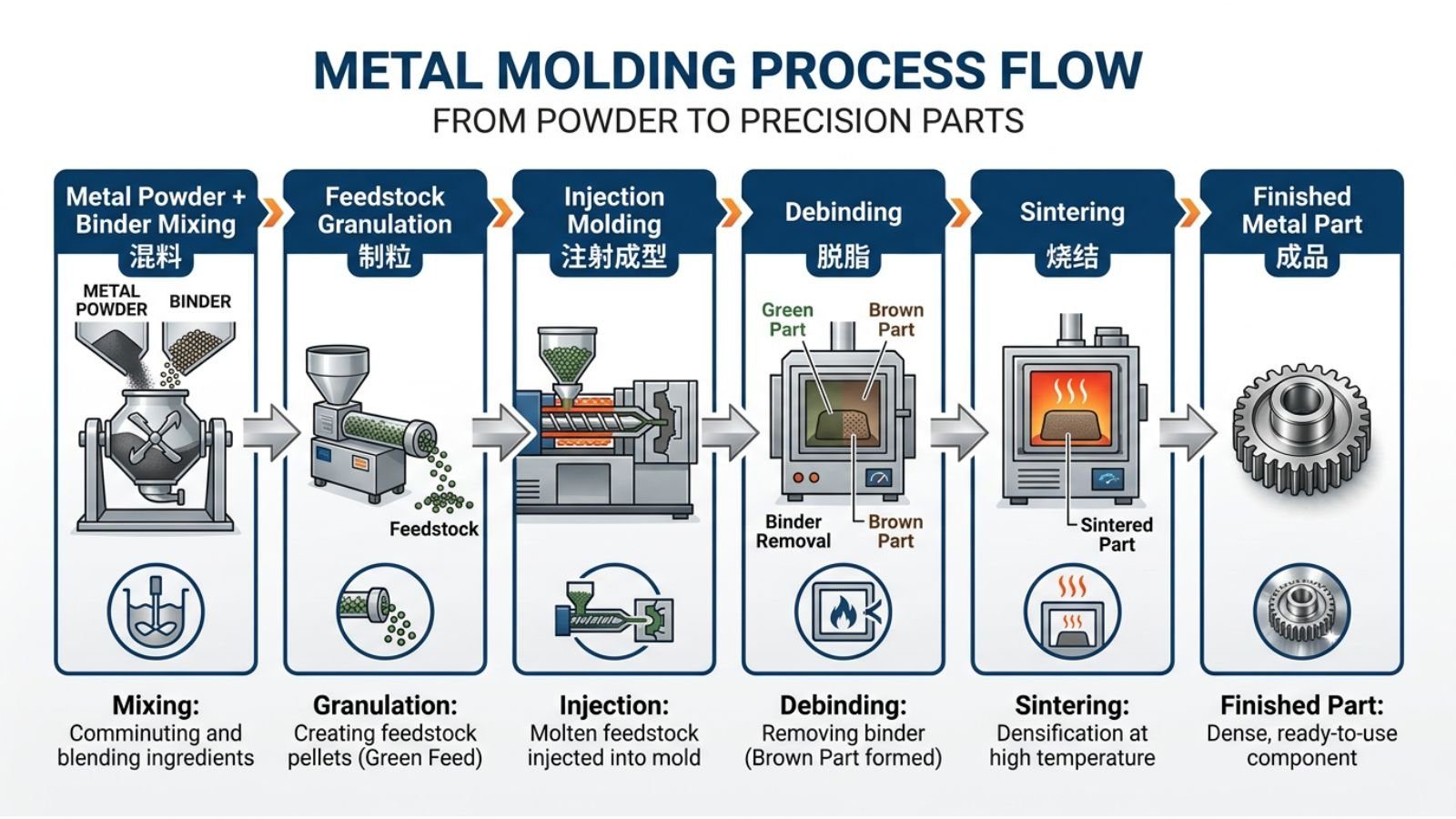
Stage 1: Feedstock Formulation
Research comparing soft magnetic alloys reveals a critical finding: Fe50Co requires50% powder loading by volume, compared to 60% for Fe50Ni or 57% for Fe-Si alloys. This lower loading is necessary because Fe50Co powder morphology creates higher intrinsic viscosity when mixed with binder.
Critical feedstock specifications for Fe50Co:
- Powder particle size:2–15 micrometers
- Powder loading:50% by volume(lower than other MIM alloys)
- Binder system:Multi-component wax/polymer backbone
- Mixing conditions:140–180°Cfor 2–4 hours with vacuum degassing
The consequence you must manage:That50% powder loadingcreates16–21% linear shrinkageduring sintering—at the upper end of typical MIM ranges. Typical production values fall between 16–19%; the 21% figure represents the upper bound and should not be used as a default design assumption. This demands:
- Precisely oversized mold cavities (18–22% oversize based on actual trial data)
- Rigorous process control to achieve ±0.3% dimensional tolerances
- MIM simulation software to predict dimensional changes
💡Practical Implication:Every 1% variation in your feedstock or sintering process translates to larger dimensional changes with Fe50Co than with other MIM alloys. Tight process control isn't optional—it's mandatory.
Stage 2: Injection Molding
MIM enables complex Fe50Co geometries impossible to machine.Critical for Fe50Co:Your mold cavities must be precisely oversized by 18–22% to compensate for high sintering shrinkage (vs. 15–18% for typical MIM alloys). Always base the exact compensation on measured shrinkage data from process trials rather than theoretical assumptions.
Key molding parameters for Fe50Co feedstock:
- Barrel temperature:150–200°C(20–30°C above binder melt point)
- Injection pressure:80–150 MPa
- Mold temperature:40–80°C
- Cooling time:10–30 seconds
- Achievable tolerance:±0.02mm on critical features after sintering
Stage 3: Debinding
Transform your green part into a porous brown part while avoiding defects. For Fe50Co, use solvent debinding followed by thermal treatment:
Proven debinding protocol:
| Stage | Method | Conditions | Purpose |
|---|---|---|---|
| Primary | Solvent (Heptane) | 50°C, 20–40 hours (scale with wall thickness; thin parts 20 hrs, thick-section parts up to 40 hrs) | Remove wax, create open pore network |
| Secondary | Thermal | Ramp 0.5–5°C/hr to600°C | Remove backbone polymer |
The solvent step creates interconnected pores that allow backbone polymer to escape as gas during thermal debinding without damaging part structure.
Stage 4: Sintering—Where Magnetic Performance Is Determined
Sintering determines whether you achieve >98% density and excellent magnetic properties—or end up with underperforming components.
Multi-stage sintering cycle for maximum performance:
| Stage | Temperature | Duration | Atmosphere | Purpose |
|---|---|---|---|---|
| Degreasing | 600°C | — | Negative pressure | Final binder removal |
| Carbon Control | 850°C | Hold | Vacuum | Critical for magnetic properties |
| Final Sintering | 1,300–1,370°C | 2–15 hours | H₂ or Ar | Densification to >98% |
Atmosphere selection matters:
- Hydrogen (preferred):Actively reduces surface oxides, improves particle bonding, achieves potentially higher final magnetic purity
- Argon:Inert protection prevents oxidation but does not remove pre-existing oxides; suitable as an alternative when hydrogen handling is a facility constraint
The density-performance relationship you must understand:
| Final Density | Achievable Bs | Explanation |
|---|---|---|
| 95–96% | ~1.8 T | Residual porosity acts as distributed air gaps, impeding flux |
| 98%+ | 2.3 T | Near-theoretical performance unlocked |
💡Critical Decision Point:For applications requiring maximum magnetic performance (Bs >2.3T), specify >98% density and consider Hot Isostatic Pressing (HIP) after sintering. HIP adds 15–30% to part cost but collapses remaining voids, pushing density toward 100%.
🎯 Key Takeaways - Processing Fe50Co:
- Lower powder loading (50% vol.vs. 60%) required → higher shrinkage (typical16–19%, upper bound21%)
- Multi-stage sintering with dedicated carbon control stage is mandatory
- Hydrogen atmosphere preferred for highest magnetic performance
- >98% density required for Bs >2.3T
- Process control requirements exceed those for standard MIM alloys
- μmax values depend heavily on post-sinter annealing; specify annealing condition when quoting permeability
Application Engineering: Where Fe50Co MIM Delivers Value
Understanding where Fe50Co MIM provides competitive advantage requires matching your application requirements against material properties.
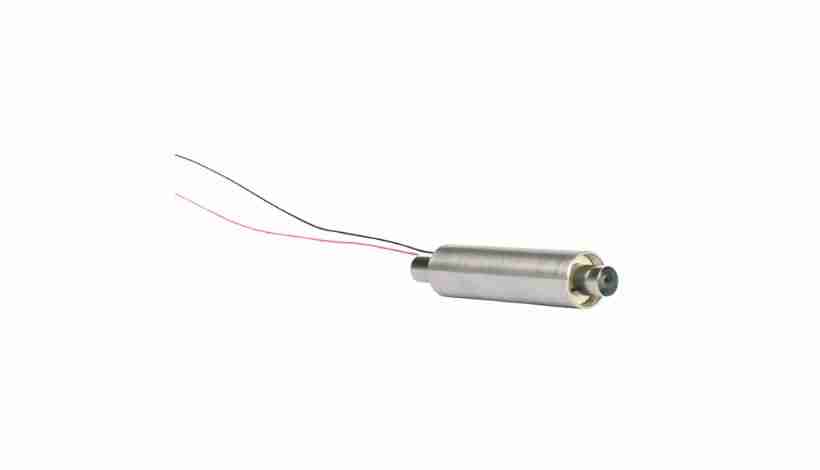
High Flux Density Applications: Motors and Actuators
Performance driver:Maximum torque or force in minimum volume
When you need maximum power density, Fe50Co's 2.3T saturation induction enables:
Direct performance benefits:
- 35–40% higher torque densityvs. silicon steel in motor design
- 50–60% size/weight reductionvs. ferrite-based actuators at equivalent force
- Reduced component weightcritical for aerospace and portable electronics
Where MIM adds value:
- Maintain ±0.02mm air gap tolerances without secondary machining
- Produce complex rotor/stator geometries in a single operation
- Integrate mounting features and flux optimization paths
- Eliminate assembly of multiple machined components
Representative applications:
- Precision servo motors for robotics (torque density limited)
- Aerospace control surface actuators (weight critical, high temperature)
- Drone motors (power-to-weight ratio paramount)
- Optical image stabilization systems (miniaturization required)
💡Engineering Insight:In a 25mm diameter motor, Fe50Co enables 40% more torque than silicon steel at the same size, or equivalent torque in a 17mm diameter motor—critical when every gram matters.
Magnetic Sensors: High Sensitivity Applications
Performance driver:Maximum response to weak magnetic fields
Your sensor's sensitivity depends on permeability and saturation headroom. Fe50Co's μmax of 5,000–8,000 (depending on whether post-sinter magnetic annealing is applied) combined with2.3Tsaturation ensures accurate sensing without premature saturation.
MIM-specific advantages:
- Complex internal flux path geometries optimize sensitivity
- Integrated mounting features reduce assembly steps
- Tight tolerances ensure consistent sensor response
- Small form factors enable miniaturization
Target applications:
- Automotive speed/position sensors (harsh environment, wide temperature range)
- Industrial proximity detection (reliability critical)
- Current sensing in power electronics (high accuracy required)
- Compass modules in consumer devices (miniaturization demanded)
High-Temperature Electronic Components
Performance driver:Reliable operation where other materials fail
Fe50Co's980–1,100°CCurie temperature enables applications impossible with alternatives:
Temperature performance comparison:
| Material | Curie Temp | Practical Continuous Operating Limit |
|---|---|---|
| Fe50Co | 980–1,100°C | 300–400°C continuous |
| Silicon Steel | ~770°C | 200–250°C continuous |
| MnZn Ferrite | <250°C | 120–150°C continuous |
Critical applications:
- Automotive under-hood sensors (150–200°C ambient)
- Aerospace avionics (wide temperature swings)
- High-power motor components (significant self-heating)
- Industrial process control sensors (elevated temperature environments)
Understanding the Frequency Limitation
Here's what you must know about Fe50Co's fundamental constraint:
Fe50Co's low electrical resistivity createseddy current losses proportional to frequency squared (∝ f²). This physics cannot be circumvented in bulk metallic alloys.
Frequency application guidelines:
| Frequency Range | Fe50Co Viability | Design Consideration |
|---|---|---|
| DC to 1 kHz | Optimal choice | Maximize power density advantage |
| 1–10 kHz | Viable with thermal management | Monitor core temperature rise |
| 10–50 kHz | Marginal | Calculate efficiency vs. size trade-off carefully |
| >50 kHz | Not recommended | Use soft ferrites instead |
💡Critical Decision Framework:If your power converter operates above50 kHz, soft ferrites will deliver better overall efficiency despite their lower saturation (0.4T vs. 2.3T). Fe50Co is optimal whenmaximizing power density at DC or low AC frequenciesis your primary constraint—not when frequency demands dominate.
Why this matters in power electronics:
Modern switch-mode power supplies increase switching frequency to reduce passive component size. However, Fe50Co's core losses grow too rapidly above20–50 kHz. Your design choice:
- High power density, low frequency (DC–10 kHz):Choose Fe50Co, accept frequency limitations
- High frequency, moderate power (>50 kHz):Choose ferrites, accept lower saturation
- No compromise exists:These requirements are met by mutually exclusive material classes
Material Selection: When Fe50Co MIM Is Your Optimal Choice
Systematic analysis of your application's critical requirements guides material selection.
Select Fe50Co MIM When:
Your application presentsallof these requirements:
- ✅Magnetic flux density is the limiting factor(need Bs >1.8T)
- ✅Operating frequency: DC to ~10 kHz(low eddy current loss critical)
- ✅High geometric complexity(3D features, internal channels, undercuts)
- ✅Thermal stability required(operating temperature >150°C)
- ✅Production volume >10,000 units/year(justify tooling investment)
- ✅Size/weight optimization is critical(aerospace, portable electronics)
Consider Alternatives When:
Choose laminated silicon steel if:
- Operating frequency: 50 Hz–5 kHz (power line to moderate AC)
- Geometry: Simple shapes amenable to lamination stacking
- Budget: Primary cost driver (Si steel costs ~1/10 of Fe50Co)
- Saturation: Bs ~1.8–2.0T sufficient for application
Choose soft ferrites if:
- Operating frequency: >50 kHz (efficiency paramount)
- Core loss: Minimum loss more important than size
- Operating temperature: <120°C (thermal limit acceptable)
- Saturation: Lower Bs (0.3–0.5T) meets requirements
Performance Comparison Matrix
Decision-making data for common alternatives:
| Property | MIM Fe50Co | Silicon Steel | Soft Ferrite |
|---|---|---|---|
| Saturation Flux (Bs) | 2.0–2.3 T | 1.8–2.0 T | 0.3–0.5 T |
| Frequency Range | DC–10 kHz | DC–5 kHz | >50 kHz |
| Curie Temperature | 980–1,100°C | ~770°C | <250°C |
| Core Loss @ 1 kHz | Moderate | Low | Very Low |
| Core Loss @ 100 kHz | Very High ❌ | High | Low |
| Geometric Complexity | Excellent (3D) | Limited (2.5D stacks) | Good |
| Relative Material Cost | Very High | Low | Moderate |
Design Optimization for Fe50Co MIM Components
Success requires designing specifically for Fe50Co's unique processing characteristics.
Wall Thickness Strategy
Recommended range: 0.5–6.0mm
- Minimum practical:0.5mm (thinner risks incomplete fill)
- Maximum recommended:6mm (thicker risks sintering defects and non-uniform shrinkage)
- Thickness transitions:Keep ratios <2:1; use gradual tapers
- Uniform thickness ideal:Ensures consistent16–21% shrinkageand minimizes warpage
💡Design Tip:Use coring to reduce mass in thick sections rather than varying wall thickness. Consistent cross-sections minimize shrinkage variation.
Dimensional Tolerance Planning
As-sintered capabilities:
- Standard tolerance:±0.3–0.5% of dimension
- Minimum tolerance:±0.05mm regardless of size
- Critical features:±0.02mm achievable with secondary grinding
Managing high shrinkage (18–22% oversize required):
Use MIM simulation software or work closely with experienced suppliers to:
- Predict shrinkage based on part geometry using actual feedstock trial data
- Account for directional variations from powder packing and gravity effects during sintering
- Optimize gate placement to minimize warpage
- Reserve secondary machining only for critical mating surfaces
Magnetic Circuit Optimization
Air gap control in magnetic assemblies:
- MIM achieves ±0.02mm on critical mating surfaces as-sintered
- Design integrated alignment features to maintain gap consistency across temperature
- Account for thermal expansion at elevated operating temperatures
- Use FEA simulation to optimize flux path geometry before tooling commitment
Flux path design principles:
- Minimize sharp internal corners (reduce magnetic reluctance concentration)
- Maintain consistent cross-sectional area throughout the flux path
- Position gates away from critical magnetic surfaces
- Consider grain orientation effects from sintering direction in high-precision applications
Troubleshooting Fe50Co MIM Performance Issues
When components don't meet specifications, systematic troubleshooting accelerates resolution.
Issue: Lower Than Expected Magnetic Properties
Most common root causes:
- Insufficient density (<98% of theoretical)
- Verify sintering temperature reached1,300–1,370°C
- Confirm adequate time at temperature (2–15 hoursdepending on part size)
- Check furnace temperature uniformity (±5°C across load)
- Consider HIP for critical applications
- Carbon or oxygen contamination
- Improve vacuum stage effectiveness at850°C
- Extend carbon control hold time
- Verify atmosphere purity (dew point <-40°C for hydrogen)
- Switch to hydrogen atmosphere for active oxide reduction
- Suboptimal microstructure / missing magnetic anneal
- Implement magnetic annealing after sintering: slow cool through600–800°C; this step can raise μmax from ~5,000 to 8,000+ and is mandatory to unlock full permeability potential
- Optimize sintering cycle to promote B2 phase formation
- Verify grain size is appropriate for the application
Diagnostic approach:
- Measure actual density via Archimedes method
- Test magnetic properties (Bs, Hc, μmax) on representative sample parts
- Perform metallographic analysis to verify microstructure and porosity distribution
- Compare against a baseline from a previously qualified process run
💡Quick Check:If Bs <2.0T, first verify density is >98%. Residual porosity is the most common cause of reduced magnetic performance.
Issue: Excessive Dimensional Variation
Fe50Co-specific causes (beyond standard MIM issues):
- Feedstock batch inconsistency(critical due to high shrinkage sensitivity)
- Implement statistical process control on feedstock viscosity
- Qualify each new feedstock lot before production release
- Monitor powder loading consistency between batches
- Sintering temperature gradients(amplified by 16–21% shrinkage)
- Map furnace temperature zones across the full working volume
- Rotate part positions between runs
- Compensate mold dimensions for known furnace gradient patterns
- Inadequate shrinkage compensation in mold design
- Re-verify mold dimensions account for 18–22% oversize
- Use actual shrinkage data from production trials, not handbook assumptions
- Consider directional (anisotropic) shrinkage variations, especially in thin-to-thick transitions
Solution hierarchy:
- Tighten feedstock acceptance criteria first
- Improve sintering temperature control second
- Compensate in mold design as last resort
Cost Analysis and Production Economics
Understanding Fe50Co MIM economics enables informed sourcing decisions.
Raw Material Cost Impact
Material pricing drivers:
- Fe50Co powder:Priced at a substantial premium per kg (volatile due to cobalt market pricing)
- Material waste via machining:60–70% becomes chips
- Material utilization via MIM:>95% in final parts
Cost per kilogram of finished parts:
- Machining:High (including waste factor)
- MIM:Far lower (minimal waste)
- Savings:Substantial per kg of finished components
💡Economic Insight:For a 10g component, material savings alone are meaningful on a per-part basis. At 50,000 units/year, that compounds into substantial annual material cost savings.
Tooling Investment Analysis
MIM tooling costs for Fe50Co components:
- Single-cavity prototype tool:Modest (quoted per project)
- Production multi-cavity tool:Substantial (quoted per project)
- Tool life:100,000–500,000+ shots depending on geometry complexity
Amortization break-even:
| Annual Volume | Tooling Amortization per Part | Break-Even vs. Machining |
|---|---|---|
| 10,000 units | Varies | Material savings offset tooling |
| 50,000 units | Varies | Clear economic advantage |
| 100,000+ units | Varies | Maximum cost efficiency |
Total Cost per Part Estimates
Approximate cost structure (10g Fe50Co component):
| Volume | Cost per Part | Primary Cost Driver |
|---|---|---|
| <5,000 units | Varies | Tooling amortization |
| 10,000 units | Varies | Tooling + processing |
| 50,000 units | Varies | Processing + material |
| 100,000+ units | Varies | Material + overhead |
Compare to machining the same part:
- Material waste cost:Substantial per part
- Machining time:5–20× longer cycle time
- Tool consumption:10–15× higher replacement rate
- Total machined cost:Substantial per part
Economic decision point:MIM becomes cost-competitive with machining at volumes >5,000–10,000 units for complex Fe50Co parts. For simple geometries where machining is more straightforward (particularly V-modified grades), the break-even rises to tens of thousands of units.
Supplier Selection: Qualifying Fe50Co MIM Capabilities
Not all MIM suppliers have the specialized expertise for high-performance Fe50Co. Use these criteria for qualification.
Essential Technical Capabilities
Verify documented experience:
- ✅Fe50Co or soft magnetic alloy track record
- Request 3+ reference customers in similar applications
- Review case studies showing achieved magnetic properties (hysteresis loop data, not just certificates)
- Verify production volumes (not just sampling capability)
- ✅Advanced atmosphere control systems
- Hydrogen or high-purity argon furnaces (not air or nitrogen)
- Dew point monitoring and control (<-40°C capability)
- Vacuum capability for the carbon control stage at 850°C
- ✅Temperature uniformity and control
- Furnace uniformity ±5°C across working zone
- Documented temperature mapping procedures with calibration records
- Data logging and statistical process control on thermal cycles
- ✅Magnetic property testing capability
- In-house VSM (Vibrating Sample Magnetometer) or B-H analyzer
- Or documented relationship with an external magnetic testing laboratory
- Ability to provide full hysteresis loops, not just pass/fail spec compliance
- ✅High-density achievement track record
- Demonstrated capability to achieve >98% density when specified
- Experience with HIP if ultra-high density is required
- Metallographic analysis capability to verify microstructure and pore distribution
Fe50Co-Specific Quality Requirements
Critical for soft magnetic alloy processing:
- Statistical process control on feedstock powder loading (50% vol.target is critical)
- Material traceability with magnetic property test results per production lot
- Documented sintering cycle control records (atmosphere purity, temperature uniformity, time at temperature)
- Batch-to-batch magnetic performance consistency verification
Supplier Partnership Approach
For new Fe50Co component development, select suppliers who:
- Provide early feasibility assessment
- Conduct mold-filling simulation before quoting
- Identify potential shrinkage or warpage issues in design review
- Offer concrete design optimization recommendations based on Fe50Co-specific experience
- Support iterative development
- Perform sintering trials to optimize magnetic properties before production tooling
- Share detailed process parameters (temperature profiles, atmosphere specifications)
- Accommodate design modifications based on initial sample results
- Demonstrate process transparency
- Provide actual sintering cycle documentation with recorded data
- Explain atmosphere control strategy and contingency for deviations
- Discuss carbon content management approach in detail
Red flag warning:Suppliers who quote Fe50Co parts without asking detailed questions about magnetic property requirements, operating conditions, or tolerance criticality likely lack specialized experience. Standard MIM processing does not produce optimal Fe50Co magnetic performance.
Establishing a Dual-Source Strategy
For production volumes >50,000 units/year:
Consider qualifying two suppliers to:
- Mitigate supply chain risk
- Maintain competitive pricing pressure
- Access different technical capabilities (e.g., one specialized in HIP, one optimized for high-volume throughput)
- Ensure business continuity
Critical requirement:Both suppliers must demonstrate equivalent magnetic property achievement and dimensional consistency through full production qualification runs before dual-source approval.
Frequently Asked Questions
Q: What makes Fe50Co superior to other magnetic materials for electronic applications?
Fe50Co offers the highest saturation magnetic induction (2.3–2.4 T) of any commercially available material—20–33% higher than silicon steel and 5–8× higher than ferrites. This enables maximum magnetic flux in the smallest possible volume, critical for miniaturized electronics. Additionally, its Curie temperature exceeds980°C, maintaining performance at temperatures where silicon steel degrades (>770°C) and ferrites fail completely (<250°C). For high-power-density applications requiring both strong magnetic fields and thermal stability, no alternative matches Fe50Co's combined performance.
Q: Why is Metal Injection Molding the preferred method for Fe50Co components?
MIM is preferred because Fe50Co's brittleness—particularly in pure binary form—makes conventional machining economically unfeasible at production volumes. Machining creates60–70%material waste as chips, destroys carbide tools within hours, and requires slow cutting speeds—all while working with powder costing a premium per kg. Even V-modified grades (Hiperco 50, Vacoflux 50) with improved ductility cannot economically match MIM's material utilization (>95%) and geometric capability for complex 3D parts at volumes above ~10,000 units. MIM delivers 5–10× lower cost per part while enabling geometries that machining cannot produce.
Q: What dimensional tolerances can I achieve with Fe50Co MIM?
As-sintered tolerances for Fe50Co MIM are typically ±0.3–0.5% of dimension with a minimum of ±0.05mm. Critical features requiring tighter tolerances (±0.01–0.02mm) can be achieved through secondary grinding on specific surfaces. The key challenge with Fe50Co is managing16–21% linear shrinkageduring sintering—higher than most MIM alloys. Work with experienced suppliers who use MIM simulation software and base mold compensation on measured trial data rather than handbook values. Always run prototype tooling to verify actual shrinkage behavior before committing to production tooling investment.
Q: At what operating frequency does Fe50Co become impractical?
Fe50Co becomes impractical above50 kHzdue to excessive eddy current losses. While it works optimally from DC to approximately 10 kHz, and is viable with thermal management between10–20 kHz, core losses typically make it unsuitable above 50 kHz. This limitation stems from low electrical resistivity causing eddy currents that grow with frequency squared (∝ f²). If your application operates above 50 kHz, soft ferrites deliver better efficiency despite lower saturation flux density (0.3–0.5T vs. 2.3T).
Q: How do I specify magnetic property requirements to suppliers?
Provide clear specifications for: (1)Minimum saturation induction (Bs)in Tesla (e.g., "Bs ≥2.2T"), (2)Maximum coercivity (Hc)in Oersteds (e.g., "Hc ≤2.0 Oe"), (3)Minimum permeability (μmax)and whether magnetic annealing is required to achieve it, (4)Operating temperature range, (5)Core loss requirementsif applicable (specify at relevant frequency and flux density). Always request actual hysteresis loop data from sample parts to verify performance, not just a certificate of conformance.
Q: What density is required for maximum magnetic performance?
To achieve Fe50Co's full potential (Bs ≥2.3T), specify>98% of theoretical density. At 95–96% density, you only achieve Bs ~1.8T because residual porosity acts as distributed air gaps that impede magnetic flux. Standard MIM sintering achieves 96–98% density. For applications demanding maximum performance, specify Hot Isostatic Pressing (HIP) after sintering, which collapses remaining voids and pushes density toward 100%. HIP adds 15–30% to part cost but unlocks the highest achievable magnetic properties.
Q: Can Fe50Co MIM components operate at elevated temperatures?
Yes—this is one of Fe50Co's key advantages. With a Curie temperature exceeding980°C, the material maintains full magnetic properties at temperatures where silicon steel degrades (>770°C) and soft ferrites fail (<250°C). Continuous operation at300–400°Cis feasible. However, for sustained operation above 300°C, consider V-modified grades (Fe49Co2V) for improved high-temperature mechanical strength. Always specify your full operating temperature range and request high-temperature magnetic property data from suppliers.
Q: What is the typical development timeline for new Fe50Co MIM components?
Expect12–18 weeks from design freeze to qualified production parts: 2–3 weeks for design review and feasibility study, 6–8 weeks for tool fabrication, 2–4 weeks for sampling and iteration, 2–3 weeks for validation testing and magnetic property qualification. Complex geometries, tight tolerances, or demanding magnetic property requirements may extend this timeline. Prototype tooling can reduce initial sampling time to 3–4 weeks but adds upfront cost (quoted per project).
Q: What minimum order quantity makes Fe50Co MIM economically viable?
Economic viability typically begins at10,000+ units annuallyto justify tooling investment (a substantial outlay for production tools). Some suppliers produce smaller quantities (1,000–5,000 units) at premium pricing. For quantities below 1,000 units, tooling cost per part becomes prohibitive (a substantial burden per part). For very low volumes, consider machining from wrought V-modified Fe50Co (where feasible) or use prototype tooling (a modest investment) if you anticipate volume ramp in the near term.
Conclusion: Strategic Implementation of Fe50Co MIM
You've now seen the technical requirements, process optimizations, and economic considerations for Fe50Co Metal Injection Molding in electronic applications. The decision to implement this technology depends on precise alignment between your application constraints and the material's strengths.
Implement Fe50Co MIM when your application requires:
- Maximum magnetic flux density (Bs >2.0T) in a size-constrained design
- Thermal stability beyond silicon steel or ferrite capabilities (>200°C)
- Complex 3D geometries impossible or prohibitively expensive to machine
- Operating frequency below ~10 kHzwhere eddy current losses remain manageable
- Production volumes exceeding 10,000 units annually to justify tooling
Consider alternatives when:
- Operating frequency exceeds 50 kHz (soft ferrites mandatory for efficiency)
- Budget constraints dominate all other factors (silicon steel is the alternative)
- Simple geometries are amenable to traditional processing
- Production volumes are below 5,000 units (machining of V-modified grades may be more economical)
Critical Success Factors
Successful Fe50Co MIM implementation requires:
- Early supplier engagementduring the design phase
- Process-specific optimization(50% vol. powder loading, 16–21% shrinkage management based on trial data)
- Rigorous quality control(>98% density verification, magnetic property testing including post-anneal characterization)
- Experienced supplier selection(documented Fe50Co track record is essential)
- Realistic timeline planning(12–18 weeks for development and qualification)
The Competitive Advantage
When your electronic system's performance is constrained by magnetic component limitations, Fe50Co MIM delivers:
- 35–40% higher power densityvs. silicon steel alternatives
- 50–60% size/weight reductionvs. ferrite-based solutions
- Reliable operationat temperatures where other materials fail
- Complex geometriesenabling design optimization impossible with conventional machining
The intersection of Fe50Co's exceptional magnetic properties and MIM's geometric capabilities creates engineering opportunities that didn't exist with conventional manufacturing. Whether you're designing compact motors for aerospace, high-temperature sensors for automotive, or miniature actuators for medical devices, understanding this technology positions you to make informed engineering decisions that deliver genuine competitive advantage.
Next steps:
- Evaluate your application against the decision criteria in this article
- Contact experienced MIM suppliers for feasibility assessment (ask specifically about Fe50Co or soft magnetic alloy production history)
- Build accurate cost models including tooling amortization and cobalt price volatility scenarios
- Conduct prototype trials to verify process stability and achieved magnetic performance
- Establish qualification protocols—including density verification and magnetic annealing conditions—before committing to production tooling
Technical Resources
Magnetic Materials Standards:
- IEC 60404 Series: Magnetic Materials Testing and Characterization
- ASTM A773: DC Magnetic Properties of Materials Using Ring and Permeameter Methods
- IEEE Std 393: Test Procedures for Magnetic Cores
Industry Organizations:
- IEEE Magnetics Society: www.ieeemagnetics.org
- ASM International: Magnetic Materials Division
Advanced Reading:
- Soft Magnetic Materials: Fundamentals, Alloys, Properties, Applications— Giselher Herzer
- IEEE Transactions on Magnetics— peer-reviewed research journal
- Journal of Magnetism and Magnetic Materials— latest developments in magnetic materials
For project-specific technical support, seek MIM suppliers with documented Fe50Co or Fe-Co-V alloy experience, in-house magnetic testing capabilities, and willingness to partner actively during development. The specialized nature of high-performance magnetic alloy processing means supplier selection is as critical as the component design itself.
Precision Metal Parts from Emitech
Nanjing Emitech delivers MIM, CNC machining, and custom metal parts. MIM services · Request a quote
Last updated: 2026-06-26