
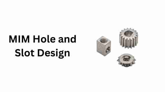
MIM part cross-section demonstrating strategic hole and slot placement for weight reduction and uniform wall thickness distribution
Key Takeaways
- Weight Reduction:Strategic placement of holes minimizes material usage without sacrificing strength.
- Wall Thickness Balance:Slots help maintain uniform wall thickness to prevent defects like sink marks.
- Mold Orientation:Designing holes perpendicular to the parting line reduces tooling complexity.
- Minimum Hole Sizes:Adhere to material-specific limits (e.g.,0.6mmfor 17-4PH) to ensure moldability.
- Sintering Shrinkage:Account for linear shrinkage factors (approx.1.20) during the design phase.
Metal Injection Molding (MIM) combines the design flexibility of plastic injection molding with the material properties of wrought metals. Hole and slot design directly impacts part weight, molding quality, and manufacturing cost. This article covers design principles, mold implications, and process optimization for MIM holes and slots.
Hole and Slot Design Functions
MIM uses fine metal powders (typically2-20 µmparticle size) mixed with thermoplastic binders. The feedstock is injected into precision molds at800-1,200 bar, then undergoes debinding and sintering to achieve95-99%theoretical density.
Holes and slots serve three primary functions:
- Functional Features:Ventilation ports, fluid channels, cable routing, or assembly alignment.
- Weight Reduction:Removing non-structural material to lower mass without compromising strength.
- Wall Thickness Uniformity:Balancing thick sections to prevent sink marks, warpage, and cracking during sintering.
Designers must optimize hole placement, diameter, and orientation based on functional requirements, load paths, and mold ejection mechanics.
Design Considerations
Weight Reduction Strategy
Strategic coring (adding holes or pockets to thick sections) reduces part weight by20-40%in typical applications. Aerospace components frequently use lightening holes in non-critical load zones to improve strength-to-weight ratios.
Finite Element Analysis (FEA) validates that coring does not compromise structural integrity under expected service loads. Stress concentrations at hole edges require chamfers or radiused entries (minimum radius0.2-0.3mm).
Wall Thickness Uniformity
Maintaining consistent wall thickness is critical for MIM process success. Sections thicker than6mmor abrupt thickness transitions exceeding2:1 ratioscause defects including sink marks, voids, and dimensional distortion.
| Wall Thickness Optimization Techniques | Description |
|---|---|
| Coring | Adding holes or pockets to thick sections to balance wall thickness |
| Ribbing | Reinforcing thin sections with ribs (60%of base wall thickness) |
| Radius Corners | Minimum0.3mminternal radius to prevent stress concentration |
Functional Integration
Holes and slots can be designed for specific performance requirements. Heat sink designs incorporate cooling fins or pin arrays to maximize surface area (achieving thermal resistance values as low as0.5 °C/W). Gears use lightening holes to reduce moment of inertia by15-25%, improving acceleration response.
Mold Design Implications
Hole orientation relative to the parting line determines mold complexity and cost. Early collaboration with tooling engineers prevents design decisions that require expensive mold modifications.
Hole Orientation Impact
- Perpendicular to Parting Line:Simplest mold design; core eject directly with minimal wear. Tooling cost baseline.
- Parallel to Parting Line:Requires side-action slides or retractable cores. Adds moderate cost to mold cost depending on feature count.
- Inclined to Parting Line:Needs angled pins, cams, or hydraulic lifters. Highest complexity; adds significant cost per mold.
Intersecting Features
Cross-drilled holes and slotted ribs complicate mold design and part ejection. Intersecting geometries often require split cores, loose inserts, or sacrificial cores that dissolve during debinding.
Simplifying hole layouts by offsetting intersections by1-2mmcan eliminate complex tooling mechanisms, reducing mold costs by20-30%.
Mold Material Selection
| Mold Material | Characteristics | Typical Applications |
|---|---|---|
| Tool Steel (H13, P20) | High wear resistance,100,000+shot life | Complex parts with tight tolerances |
| Aluminum (7075-T6) | Lower cost, faster thermal cycling,10,000-25,000shot life | Prototypes, low-volume production |
| Copper Alloys (BeCu) | Excellent thermal conductivity,50,000+shot life | Thin-walled parts, long flow paths |
Design Best Practices
Design for Manufacturability (DFM)
- Minimize Feature Count:Consolidate holes and slots to reduce mold complexity and maintenance.
- Standardize Diameters:Use common drill sizes (metric: 0.5, 0.6, 0.8, 1.0mm increments) to lower tooling costs.
- Avoid Undercuts:Design holes with1-2°draft angle for self-ejection, eliminating side-actions.
- Follow Material Limits:Adhere to minimum feature sizes based on powder rheology and binder viscosity.
Material-Specific Design Rules
| Material | Minimum Hole Diameter | Draft Angle Requirement |
|---|---|---|
| 17-4PH Stainless | 0.6mm | 1°per side |
| Ti-6Al-4V | 0.8mm | 1.5°per side |
| MIM-2200 (Low Alloy Steel) | 0.5mm | 0.8°per side |
Simulation-Driven Validation
CAD-integrated simulation tools optimize hole and slot designs before tooling fabrication:
- Moldflow Analysis:Predicts filling patterns, identifies short shots or air traps, optimizes gate locations and runner sizing.
- Finite Element Analysis (FEA):Validates that coring does not reduce part strength below design safety factors (typically1.5-2.0×working stress).
- Sintering Simulation:Estimates dimensional changes during densification, allowing mold cavity adjustments to compensate for anisotropic shrinkage.
Sintering Shrinkage Reference
Use this reference guide to estimate final part dimensions after sintering. Shrinkage factors apply linearly in all three axes.
| Material | Shrinkage Factor | Green Cavity (mm) | Sintered Part (mm) |
|---|---|---|---|
| 316L Stainless | 1.20 | 10.00 | 8.33 |
| 20.00 | 16.67 | ||
| 30.00 | 25.00 | ||
| 17-4PH Stainless | 1.18 | 10.00 | 8.47 |
| 20.00 | 16.95 | ||
| 30.00 | 25.42 | ||
| M2 Tool Steel | 1.22 | 10.00 | 8.20 |
| 20.00 | 16.39 | ||
| 30.00 | 24.59 |
Early Supplier Involvement (ESI)
Engage MIM suppliers during the design concept phase to validate manufacturability. Engineers will assess core pin diameter-to-length ratios (avoid exceeding8:1to prevent pin deflection), draft angle adequacy, and gate placement to minimize weld lines at hole intersections.
Regular design reviews catch issues early, reducing prototype iterations and accelerating time-to-market.
Quality Control & Process Optimization
Dimensional Control
Maintaining tight tolerances on holes and slots requires precision across the entire MIM process chain:
- Mold Cavity Precision:EDM or CNC machining to±5 µmtolerance, followed by polishing toRa 0.2-0.4 µmsurface finish.
- Molding Parameters:Optimize injection pressure (800-1,200 bar), melt temperature (150-200°Cdepending on binder), and holding time to ensure complete cavity fill.
- Debinding & Sintering Control:Maintain atmosphere composition (95% N₂ / 5% H₂for stainless steels) and temperature profiles (±5°Ctolerance) to minimize distortion.
Common Defect Prevention
| Defect Type | Root Cause | Prevention Method |
|---|---|---|
| Sink Marks Near Holes | Uneven wall thickness, insufficient packing pressure | Add ribs at60%of base wall thickness; increase holding pressure by10-15% |
| Flash at Hole Edges | Excessive injection pressure, worn core | Reduce injection speed by15-20%; inspect and replace worn tooling components |
| Hole Diameter Variation | Inconsistent sintering shrinkage, thermal gradients | Improve furnace uniformity (±3°Czone control); use sintering setters to constrain warpage |
Process Optimization Methods
Statistical process control and machine learning improve part quality and production efficiency:
- Design of Experiments (DOE):Taguchi methods identify critical process variables (injection pressure, mold temperature, holding time) and their interactions.
- Statistical Process Control (SPC):Real-time monitoring of cavity pressure, melt temperature, and cycle time detects process drift before defects occur.
- Machine Learning (ML):Predictive models trained on historical data optimize process settings for new part geometries, reducing trial-and-error iterations.
Solvent Debinding Parameters (Typical for Wax-Based Binders):
- Temperature:60°C ± 2°C
- Immersion Time:8-10 hours
- Target Weight Loss:92-95%of binder removed
Mold Maintenance
Preventive maintenance extends mold life and maintains part quality:
- Scheduled Cleaning:Remove residual feedstock and release agent buildup every5,000-10,000 shots.
- Core Pin Inspection:Measure diameter wear using pin gauges; replace when wear exceeds0.02mm.
- Performance Monitoring:Track cycle time increases (indicating wear) and defect rates to trigger corrective maintenance before quality degrades.
Application Case Studies
Automotive: Fuel Injector Nozzle
Component:6-hole direct injection nozzle for high-pressure fuel systems
Technical Specifications:
- Material:440C stainless steel (hardness58-60 HRCafter heat treatment)
- Critical Features:Six spray orifices atØ0.15mm, internal fuel galleries, conical sealing surfaces
- Tolerances:Spray hole concentricity±0.02mm, surface finishRa 0.8 µm
MIM Advantages:
- Lower manufacturing cost compared to multi-axis CNC machining
- Spray pattern consistency improved across production lots
- Fuel atomization efficiency improved, contributing to better combustion and emissions
Medical: Laparoscopic Surgical Scissors
Component:Articulating scissors for minimally invasive surgery
Technical Specifications:
- Material:17-4PH stainless steel (biocompatible per ISO 10993)
- Critical Features:Micro-holes (Ø0.3mm) on blade edges for electrocautery wire routing, precision hinge joint with±0.03mmradial clearance
MIM Advantages:Integrated electrocautery channels eliminate secondary drilling operations, reducing manufacturing time substantially. Hinge joint formed in-situ during molding, improving alignment accuracy and reducing assembly labor.
Electronics: Smartphone Camera Lens Mount
Component:Dual-camera lens holder for flagship smartphone
Technical Specifications:
- Material:Ti-6Al-4V titanium alloy
- Critical Features:Precision bores (Ø8.5mm ±0.015mm) for lens barrels, M1.4 threaded mounting holes, lightweighting slots reducing mass substantially
MIM Advantages:Titanium's low density (4.43 g/cm³) combined with strategic coring achieves target weight (1.2g) while maintaining structural rigidity. Integrated lens barrel bores eliminate post-machining, preserving optical alignment tolerances.
Emerging Technologies
Hybrid AM-MIM Processes
Binder jetting additive manufacturing creates complex green parts that undergo conventional MIM debinding and sintering. This hybrid approach enables geometries impossible with traditional molding (e.g., internal lattice structures, conformal cooling channels) while maintaining MIM's material properties and surface finish.
Micro-MIM
Micro-MIM produces parts with features as small as0.1mmand total dimensions under5mm. Applications include micro-gears for medical robotics, watch components, and fiber-optic alignment sleeves. Specialized feedstocks with sub-micron powders (0.5-2 µm) enable these miniaturized geometries.
Sustainable Manufacturing Practices
Environmental initiatives improving MIM sustainability:
- Feedstock Recycling:Reprocessing sprues, runners, and reject parts recovers95-98%of material, minimizing waste.
- Water-Based Binders:Replacing solvent-based binders with aqueous systems eliminates VOC emissions and simplifies debinding waste treatment.
- Energy Recovery:Heat exchangers on sintering furnaces preheat incoming parts, reducing total energy consumption by12-18%.
Conclusion
Hole and slot design directly impacts MIM part functionality, manufacturability, and cost. Strategic coring reduces weight while maintaining structural integrity. Uniform wall thickness prevents molding defects. Hole orientation optimizes tooling complexity and cost.
Designers must collaborate with MIM engineers during the concept phase to validate feature feasibility, optimize mold design, and establish process control parameters. Simulation tools predict filling behavior, structural performance, and sintering shrinkage before tooling fabrication.
As MIM materials expand (including low-density alloys, magnetic alloys, and bioceramics) and process controls tighten (real-time cavity pressure monitoring, closed-loop sintering atmosphere control), adoption will accelerate across high-performance applications requiring complex, net-shape metal components.
Frequently Asked Questions
Q: What is the minimum recommended hole size for MIM?
Minimum hole diameter depends on material powder size and binder rheology:
- 17-4PH Stainless Steel:0.6mm minimum
- MIM-2200 Low Alloy Steel:0.5mm minimum
- Ti-6Al-4V Titanium:0.8mm minimum (larger due to powder flowability constraints)
Holes smaller than these limits risk incomplete filling, weak core , or pin breakage during ejection. For micro-features below0.3mm, consult MIM suppliers specializing in micro-MIM processes.
Q: How much does MIM material shrink during sintering?
Linear shrinkage typically ranges from15-20%depending on powder loading and sintering conditions. Common shrinkage factors:
- 316L Stainless:1.20× (16.7% shrinkage)
- 17-4PH Stainless:1.18× (15.3% shrinkage)
- M2 Tool Steel:1.22× (18.0% shrinkage)
A 10mm mold cavity dimension produces an 8.33mm final part in 316L. Shrinkage is generally isotropic (uniform in all directions) but can vary by±0.5%between axes depending on part geometry and gate location. Always validate shrinkage factors with initial prototype runs.
Q: Why is hole orientation important in MIM mold design?
Hole orientation determines ejection mechanics and tooling cost. Holes perpendicular to the parting line use simple core that retract during mold opening. Parallel or inclined holes require side-actions (slides, lifters, or cams) that actuate perpendicular to the main ejection direction.
Side-action tooling adds moderate-to-significant cost per mold depending on complexity. For high-volume production (>100,000 parts annually), this tooling cost is justified. For lower volumes, redesigning holes to perpendicular orientation can improve project economics.
Q: Can I create intersecting holes in MIM parts?
Yes, but intersecting features require complex tooling. Cross-holes typically need split cores or loose inserts that assemble before injection and disassemble during ejection. This increases mold cost by25-40%and extends lead time by2-3 weeks.
Design alternatives that reduce complexity:
- Offset intersections by 1-2mm:Eliminates core splitting requirements
- Use external slots instead of through-holes:Simplifies ejection mechanics
- Accept post-machining for low-volume intersections:Often more economical than complex tooling for <10,000 annual volume
Always review intersecting features with MIM engineers during the quotation phase to optimize manufacturability versus cost.
Precision Metal Parts from Emitech
Nanjing Emitech delivers MIM, CNC machining, and custom metal parts. MIM services · Request a quote
Last updated: 2026-06-24