
Sintered Metals for EVs
Electric vehicle motors face three critical engineering constraints: excessive weight that limits range, thermal management challenges that throttle performance, and geometric limitations imposed by two-dimensional magnetic flux paths. Sintered metal technology can address all three by enabling significant weight reduction through net-shape design, superior heat dissipation through complex internal geometries, and three-dimensional motor designs that can improve efficiency in certain motor designs.
This technical analysis examines why leading EV manufacturers are transitioning from traditional metalworking to powder metallurgy for critical powertrain components, and what design considerations you must understand to leverage this manufacturing revolution.
Understanding Powder Metallurgy: The Manufacturing Foundation
Powder metallurgy (PM) creates precision metal components by compacting metal powders under high pressure, then heating them to fuse the particles through solid-state diffusion—critically, without melting the material into liquid form. This net-shape process distinguishes PM from casting (which requires melting) and forging (which requires massive deformation of solid billets).
The Three-Stage Process
Stage 1: Powder Formulation
You start with engineered metal powders—typically iron, copper, stainless steel, or aluminum—blended with alloying elements (nickel, molybdenum, carbon) to achieve target properties. Lubricants reduce friction during compaction, while the powder particle size distribution (typically 5-150 micrometers) directly controls final density and mechanical properties.
The critical requirement: complete homogeneity in the powder blend. Any inconsistency will manifest as property variations in your finished components.
Stage 2: Compaction
The powder mixture flows into a precision die cavity where hydraulic or mechanical presses apply 400-800 MPa of pressure—roughly 30-60 tons per square inch. This immense force mechanically interlocks the particles, creating a "green compact" with sufficient strength for handling but minimal structural integrity (comparable to chalk or unbaked ceramic).
Your green part achieves dimensional accuracy within ±0.3% of final specifications, with density approximately 80-90% of theoretical maximum.
Stage 3: Sintering
The transformative step occurs when you heat the green compact in a controlled-atmosphere furnace to 70-90% of the base metal's melting point (typically 1120-1250°C for steel). At this temperature, solid-state atomic diffusion creates metallurgical bonds between powder particles, dramatically increasing strength, density, and hardness.
Critical process control:The furnace atmosphere—typically nitrogen-hydrogen blends or dissociated ammonia—must prevent oxidation. Any oxygen contamination creates surface oxides that block particle bonding, resulting in weak, defective parts. This reducing atmosphere also removes existing surface oxides and controls final carbon content.
The result: a fully bonded metal component with properties tailored to your application requirements, ready for use or secondary operations like machining, heat treatment, or coating.
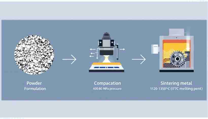
Figure 1: The powder metallurgy process transforms metal powder into precision-engineered components through compaction and sintering
Video: Comprehensive overview of the powder metallurgy process including powder manufacture, blending, compacting, and sintering (Video: The Engineering Science)
Video: Animation showing how sintering bonds metal powder particles through controlled heating below melting point (Video: Omnidex Group)
Why Electric Vehicles Create the Perfect Application for Sintered Metals
If you're engineering electric vehicles, you face engineering challenges that make powder metallurgy not just beneficial but increasingly essential. The specific demands of electric powertrains create conditions where PM's unique capabilities deliver measurable competitive advantages.
📌KEY DRIVERS:
•Weight-Range equation:Reducing vehicle mass improves EV efficiency and can extend driving range; the exact relationship depends on vehicle design and duty cycle
•Thermal loads:Battery, motor, and inverter heat management is critical for performance and service life
•Motor efficiency targets:High-efficiency motors benefit from advanced magnetic materials with 3D flux capability
•Cost pressure:EVs must achieve competitive cost structures to reach mass-market adoption
The Lightweighting Imperative
Vehicle weight directly impacts your EV's range. Reducing mass generally improves efficiency and can extend driving range, although the exact benefit depends on vehicle size, battery capacity, and driving conditions.
Powder metallurgy contributes through two mechanisms:
Inherent Density Advantage:Sintered steel components with 5-10% controlled porosity have density of 7.0-7.4 g/cm³ compared to 7.85 g/cm³ for wrought steel—an immediate 6-11% weight reduction for equivalent volumes.
Topology Optimization:More significantly, PM's net-shape capability allows you to design components with material placed only where structural analysis indicates necessity. You can create complex geometries—internal lightening features, variable cross-sections, integrated mounting points—that would require extensive machining or would be geometrically impossible through conventional methods.
System-Level Impact:Replacing multiple structural components with optimized sintered equivalents can reduce overall system weight. The cumulative effect across a production fleet can contribute to improved range and efficiency, but must be validated for each specific vehicle program.
Thermal Management Performance Requirements
Your EV thermal management system must control heat from three primary sources: battery packs during fast charging and high-power discharge, inverter and power electronics switching losses, and electric motor resistive and core losses. Inadequate thermal control causes:
- Battery capacity fade and shortened lifespan
- Electronic component failure or thermal throttling
- Motor efficiency degradation and potential permanent magnet demagnetization
Sintered metals address these challenges through design capabilities impossible with traditional manufacturing:
Complex Internal Geometries:You can design coolant passages, heat exchange channels, and fluid distribution manifolds directly into sintered parts during compaction—features requiring assembly of multiple machined pieces or completely unachievable in cast components.
Gerotor Pump Rotors:Electric coolant pumps for battery and motor cooling predominantly use gerotor-style positive displacement designs. The inner and outer rotors feature complex lobed tooth profiles requiring precise clearances. PM is your most cost-effective method for producing these rotors at automotive volumes, delivering necessary geometric precision while enabling secondary hardening for wear resistance.
Tailored Thermal Properties:Through selective alloying and density management, you can engineer thermal conductivity to match application requirements—higher conductivity for heat sinks, controlled conductivity for thermal barriers.
Electric Motor Efficiency Targets
When you design EV motors, you're targeting specific performance metrics: high power density, high efficiency across the operating range, and torque density sufficient for acceptable vehicle acceleration. Achieving these targets with traditional laminated steel stator and rotor cores imposes significant design constraints.
Powder metallurgy delivers its most revolutionary impact through Soft Magnetic Composites (SMCs)—a specialized class of materials that fundamentally changes what's possible in electric motor design.
Soft Magnetic Composites: Breaking the Century-Old 2D Constraint
The Fundamental Problem with Laminated Steel
When you build conventional electric motors, you stack 200-300 thin silicon-iron steel sheets (laminations), each insulated from its neighbors. This construction exists for one reason: eddy current loss mitigation.
As magnetic flux changes in the motor, it induces electrical currents in any conductive material. In a solid steel core, these "eddy currents" would flow in large loops, generating significant heat and reducing efficiency. Laminations confine eddy currents to thin individual sheets where path length and resistance losses are minimized.
However, this solution imposes a severe design constraint:magnetic flux must flow parallel to the lamination plane—a two-dimensional flux path.Any significant flux component perpendicular to laminations would cross multiple sheets, inducing large inter-lamination currents and causing catastrophic losses.
This 2D constraint has dictated electric motor topology for over a century, restricting you to radial flux designs where magnetic fields flow in a plane perpendicular to the motor shaft.
How SMCs Enable 3D Magnetic Flux Paths
Soft Magnetic Composites solve this limitation at the particle level. In SMC production, you coat individual iron powder particles (typically 50-200 micrometers diameter) with a thin electrically insulating layer—iron phosphate or organic polymer films just nanometers thick.
When you compact and sinter these coated particles, the result is a bulk magnetic material where every particle is electrically isolated from its neighbors. This particle-level insulation confines eddy currents to microscopic scales, dramatically reducing losses even at high frequencies.
The Revolutionary Advantage:Because insulation is isotropic (uniform in all directions), magnetic properties are also isotropic. You can now design motors withthree-dimensional magnetic flux pathswithout incurring the eddy current penalties that would destroy laminated steel motor performance.
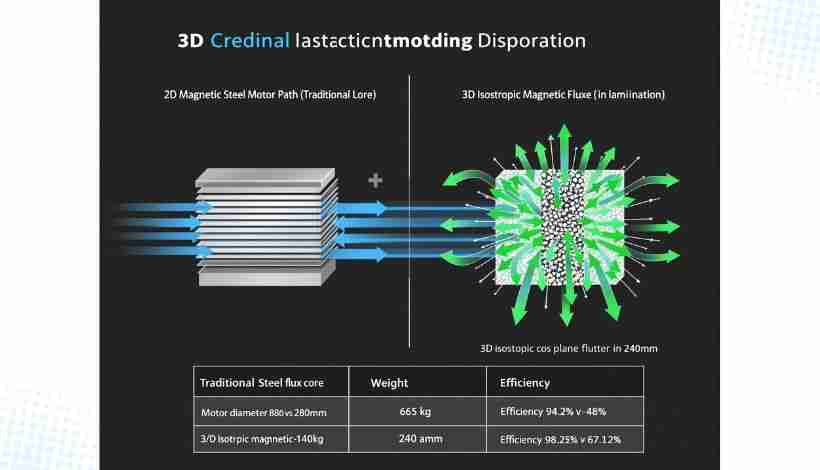
Figure 2: Soft Magnetic Composites enable three-dimensional magnetic flux paths, eliminating the 2D constraint of traditional laminated steel cores
Quantified Performance Improvements
When you implement SMCs in motor core design, you unlock measurable benefits:
1. Novel Motor Topologies
You can now design:
- Axial flux motors:Magnetic flux travels parallel to the motor shaft between disc-shaped stator and rotor assemblies. These pancake motors can achieve higher torque density than equivalent radial flux designs in some implementations.
- Transverse flux motors:Feature flux paths wrapping around motor circumference, enabling extremely high torque production in compact packages.
- Claw-pole designs:With complex 3D flux paths impossible to realize with laminations.
These topologies were previously impractical or impossible with laminated steel. SMCs make them production-viable.
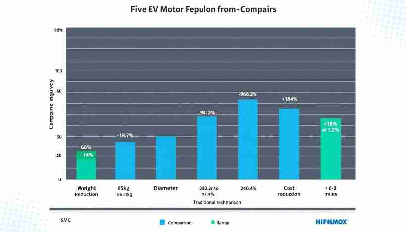
2. Reduced Motor Size and Weight
Three-dimensional flux optimization allows you to:
- Reduce stator yoke thickness by allowing flux to flow in optimal paths rather than remaining constrained to 2D
- Shorten copper end-turn length through compact winding placement
- Decrease overall motor diameter for equivalent power output in some designs
Actual performance gains depend on motor topology, power rating, operating conditions, and system integration. Application-specific modeling and prototyping are required to quantify size, weight, efficiency, and cost benefits.
3. Improved High-Frequency Performance
Modern EV inverters increasingly use silicon carbide (SiC) semiconductors switching at 20-40 kHz (versus 8-12 kHz for traditional silicon IGBTs). At these elevated frequencies, laminated steel core losses increase significantly.
SMCs maintain lower core losses at high frequencies due to superior eddy current suppression. When you implement SiC inverters, SMC motor cores maintain or improve efficiency while inverter switching frequency increases.
4. Manufacturing Efficiency
From a production standpoint, you form complex SMC stator and rotor geometries in a single press-and-sinter operation. This replaces the labor-intensive process of stamping hundreds of individual laminations, stacking with precise alignment, then interlocking or welding into a core assembly.
Result:lower labor costs, higher dimensional accuracy, faster production throughput.
5. End-of-Life Recyclability Advantage
Motor recycling presents a significant challenge with laminated cores. Separating tightly bonded copper windings from steel stacks is economically impractical, typically resulting in contaminated steel scrap that loses copper value.
SMCs solve this: the brittle sintered core crumbles easily in crushing equipment, completely liberating copper windings for high recovery rate. This aligns perfectly with circular economy principles and represents a major sustainability advantage.
SMC Limitations You Must Consider
While transformative, SMCs have trade-offs requiring evaluation:
- Higher DC Hysteresis Loss
- SMC materials have 3-5× higher hysteresis losses than grain-oriented electrical steel at low frequencies. For motors operating predominantly at low speeds, laminated steel may still be more efficient.
- Lower Saturation Flux Density
- SMCs typically saturate at 1.4-1.6 Tesla versus 1.8-2.0 Tesla for silicon steel. This may require larger core cross-sections to avoid saturation, partially offsetting size advantages.
- Higher Material Cost
- SMC powder and processing currently cost more than electrical steel laminations at equivalent volumes. Economic breakeven depends on production volume and value you place on design freedom and weight savings.
Your Design Recommendation:Conduct application-specific analysis comparing total system cost, performance, and efficiency rather than making decisions based solely on material cost per kilogram.
Critical EV Components Enabled by Sintered Metals
Understanding where PM delivers maximum value helps you make informed design and sourcing decisions across EV subsystems.
📌KEY APPLICATIONS:
•E-axle transmissions:Planetary gears, carriers, parking locks
•Thermal management:Pump rotors, heat exchangers, cooling plates
•Motor cores:SMC stators and rotors for axial/transverse flux designs
•Power electronics:Reactor cores, structural components, busbars
•Chassis systems:Brake-by-wire and steer-by-wire actuators
E-Axle and Transmission Components
Planetary Gearsets
Single-speed reduction gearboxes in EVs commonly use planetary gear arrangements achieving 8:1 to 12:1 reduction ratios in compact packages. Sintered metal components include:
- Sun gears:Central gear meshing with all planet gears
- Planet gears:Typically 3-4 gears orbiting the sun gear
- Planetary carriers:Structural component holding planet gears in position
For planetary carriers specifically, advanced sinter-joining techniques enable you to create complex hollow structures with integrated bearing journals and mounting features in a single operation. This design approach can reduce component count and assembly steps compared with welded assemblies, while also contributing to weight savings. The actual benefit varies with part complexity and production volume.
Consolidating a multi-piece welded carrier into a single sintered component can reduce assembly steps, part count, and weight. The actual savings depend on part geometry, production volume, and the specific baseline design.
Parking Lock and Synchronizer Components
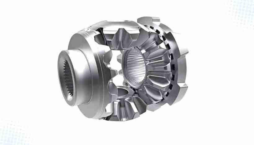
Parking lock systems require components fitting within tight gearbox packaging while providing reliable mechanical locking. Sintered metal's net-shape capability produces parking gears, pawls, and actuator brackets with complex non-symmetrical geometries requiring extensive 5-axis machining if produced from billet material.
For multi-speed transmissions (increasingly common in performance EVs and commercial vehicles), sintered synchro hubs and keys provide precise internal and external spline forms required for engagement, with selective surface hardening through induction heating achieving wear-resistant surfaces while maintaining tough cores.
Thermal Management System Pumps
Electric Coolant Pump Rotors
Your EV cooling system requires multiple pumps: motor coolant circulation, battery thermal management, cabin HVAC, and potentially dedicated inverter cooling. Most applications use compact gerotor pumps.
Gerotor pumps consist of an inner rotor (typically 6-7 lobes) rotating inside an outer rotor (7-8 lobes). The mathematical curves defining these lobes—epitrochoidal or cycloid profiles—must maintain precise clearances (0.05-0.15mm) while operating at 3,000-6,000 RPM.
Why PM is optimal:
- Complex lobe geometry forms directly in compaction die with no secondary machining
- Production rates exceed 1,000 pieces per hour on automated presses
- Material utilization is typically high, with less scrap than machined rotors
- Achieves necessary surface finish and dimensional accuracy without grinding
- Sinter-hardening can achieve 40-50 HRC surface hardness for extended pump life
Motor and Power Electronics Applications
Stator and Rotor Cores (SMC)
When you specify SMC cores for axial flux or transverse flux motors, you're typically working with materials like:
- Iron-based SMCs with phosphate insulation coatings (cost-sensitive applications)
- Polymer-bonded iron powder composites (superior high-frequency performance)
- Hybrid SMCs with amorphous metal particle additions (premium performance applications)
Reactor Cores for DC-DC Converters
Your EV's power control unit includes boost converters stepping up battery voltage to 600-800V levels required by traction inverters. Magnetic reactors (inductors) in these converters use sintered powder cores achieving:
- High saturation flux density for compact size
- Low core losses at 50-150 kHz switching frequencies
- Thermal stability across -40°C to +150°C operating temperatures
Chassis and Control System Actuators
Brake-by-Wire and Steer-by-Wire Systems
When you implement "X-by-wire" technologies replacing mechanical linkages with electronic actuation, you need compact high-torque actuators. These typically use:
- Multi-stage planetary gearboxes with sintered gears achieving 100:1 to 400:1 ratios
- Sintered rack components for linear motion conversion
- High-strength sintered structural brackets and housings
PM's ability to produce complex gear geometries with integrated features (flanges, bearing journals, splines) in single operations makes it essential for achieving cost and weight targets these systems require.
Economic Analysis: When Sintered Metals Make Sense
Understanding the economic breakeven point helps you evaluate whether to specify sintered components for your application. Actual costs and savings vary widely with part geometry, material, annual volume, and regional labor rates.
📌COST FACTORS:
•Initial tooling:PM requires compaction tooling; investment increases with part complexity
•Piece part cost:At production volumes, sintered parts can be significantly lower cost than fully machined equivalents
•Break-even:Break-even volume depends on the cost differential versus the alternative process and tooling investment
•Annual savings:Multi-part powertrain assemblies can generate meaningful savings at automotive volumes, but must be calculated per program
Tooling Investment Requirements
Your initial investment for PM production includes precision-ground hardened steel dies, punches, and core rods. Tooling cost rises with part complexity, number of levels, and required tolerances. Simple cylindrical parts require less expensive tooling than multi-level carriers or intricate pump rotors. Request a detailed quotation from your PM supplier to understand the tooling investment for a specific component.
Piece Part Cost Comparison
Once tooling is amortized, per-part costs depend on material, part size, cycle time, and secondary operations. Sintered steel gears often cost significantly less than equivalent machined-from-bar-stock gears at volume, because PM avoids most machining time and reduces material scrap. The exact advantage varies by part and should be confirmed with supplier quotations for your specific design and annual volume.
Break-Even Volume Analysis
PM becomes economically favorable when accumulated piece-part savings exceed the initial tooling investment. Higher annual volumes and larger cost differentials versus machining shorten the payback period. For automotive programs producing tens of thousands of vehicles per year, break-even is often reached quickly when multiple sintered components are adopted across the powertrain.
Total Cost of Ownership Benefits
Beyond piece part cost, you should evaluate:
Inventory and Logistics:Net-shape PM parts reduce SKU complexity. A sintered component with integrated features replaces 3-5 machined and assembled pieces, simplifying inventory management and reducing assembly floor space.
Quality and Warranty Costs:PM's process consistency (tight control of powder chemistry, compaction pressure, sintering atmosphere) can deliver good part-to-part uniformity. Warranty performance depends on design, process control, and application; compare historical data from your supplier rather than assuming a fixed advantage.
Supply Chain Resilience:PM suppliers can often provide competitive lead times and volume flexibility, but actual performance varies by supplier, region, and market conditions. Include lead-time and capacity commitments in supplier qualification.
Technical Limitations and When NOT to Use Powder Metallurgy
Making informed engineering decisions requires understanding not only where PM excels but also where limitations exist or alternative processes may be superior.
📌KEY LIMITATIONS:
•Porosity:Residual 5-15% porosity reduces strength and fatigue life
•Fatigue performance:50-70% of wrought material fatigue strength
•Size constraints:Practical limits around 250mm diameter, 150mm height
•Material restrictions:Some alloys difficult or expensive to process via PM
Inherent Material Constraints: The Porosity Challenge
Sintered components typically retain 5-15% residual porosity even after full sintering. This directly affects mechanical properties:
- Tensile strength:Sintered steel achieves 70-85% of equivalent wrought steel strength
- Ductility:Elongation at failure significantly reduced (2-5% vs. 15-25% for wrought steel)
- Impact toughness:Charpy impact values 40-60% lower than wrought materials
- Fatigue strength:Most significant limitation—fatigue endurance limits typically 50-70% of wrought materials
Pores act as stress concentration sites and crack initiation points, making sintered parts more susceptible to fatigue failure under cyclic loading.
When This Matters:
- High-cycle fatigue applications (>10⁷ cycles) with significant stress reversals
- Impact-loaded components in safety-critical systems
- Pressure vessels or hermetically sealed components (porosity creates leak paths)
Mitigation Strategies:
- Copper infiltration: Fills pores with molten copper, increasing density and improving strength
- Hot isostatic pressing (HIP): Applies high pressure and temperature simultaneously for near-full density
- Resin impregnation: Seals surface porosity for improved corrosion resistance
However, these secondary processes add cost and processing time, reducing PM's economic advantage.
Fatigue Performance: Sintered vs. Forged Components
For components experiencing millions of stress cycles—connecting rods, suspension arms, heavily loaded gear teeth—you must critically evaluate whether PM can meet fatigue life requirements.
Comparative Fatigue Data(equivalent steel compositions):
- Forged component: Fatigue limit is typically higher than sintered equivalents
- Sintered component (as-sintered): Fatigue limit is generally a fraction of forged material, often in the range of 50-70% depending on density and microstructure
- Sintered component (copper-infiltrated or HIP): Fatigue performance improves toward wrought levels but rarely matches forging
Why Forging Wins for Fatigue-Critical Parts:
Forged components have:
- near-full density with no internal defects or pores
- Grain flow aligned with component geometry providing directional strength
- Work-hardened surface layers resisting crack initiation
- Superior resistance to crack propagation through continuous grain structure
Your Decision Framework:
Use forging when:
- Component experiences high-cycle fatigue (>10⁶ cycles to failure)
- Stress levels approach 60-70% of material yield strength
- Failure consequences are severe (safety-critical systems)
- Production volume justifies forging die investment
Use PM when:
- Fatigue stresses are moderate (<40% of yield strength)
- Cycle counts are lower (<10⁶ cycles)
- Geometric complexity makes forging impractical or expensive
- High production volume (>100,000 units) enables cost amortization
Process Limitations Affecting Design Freedom
While PM offers excellent design freedom for complex shapes, limitations exist:
Size Limits:Practical maximum part size is constrained by press tonnage. Most automotive parts are produced on 400-800 ton presses, limiting maximum projected area to approximately 150-250 cm². Larger components require assembly of multiple sintered pieces.
Aspect Ratio Limits:Long thin features (length-to-width ratios >3:1) are difficult to compact uniformly. Density variations can cause cracking during sintering.
Undercuts and Cross-Holes:Features preventing part ejection from die require complex multi-action tooling (significantly increasing cost) or secondary machining operations (reducing PM's economic advantage).
Threads:Internal threads cannot be directly formed in PM. You must either machine threads post-sintering, use thread-rolling operations, or design for self-tapping or press-fit inserts.
Thin Walls:Minimum practical wall thickness is approximately 1.5-2.0mm. Thinner sections are difficult to fill uniformly with powder and may lack structural integrity.
Frequently Asked Questions
Q: Can sintered metal parts match the strength of forged or cast components?
For most EV applications, yes—with appropriate design and material selection. Sintered parts typically achieve 70-85% of equivalent wrought material tensile strength. Through advanced techniques (copper infiltration, warm compaction, ultra-high-temperature sintering), you can reach 85-95% of wrought strength.
The critical distinction is fatigue performance: sintered parts generally exhibit 50-70% of forged fatigue strength due to residual porosity. For non-fatigue-critical applications or where fatigue stresses are moderate, sintered components fully meet requirements. For high-cycle fatigue applications with peak stresses approaching material yield strength, carefully evaluate whether PM can meet life requirements or consider forging.
Q: How does the porosity in sintered parts affect performance in EV applications?
Porosity has both negative and positive implications:
Negative effects:
- Reduces tensile strength, ductility, and fatigue life
- Can create leak paths in pressure-containing applications
- May allow corrosion in harsh environments
Positive effects:
- Reduces weight (important for range)
- Enables self-lubrication when impregnated with oil (extending bearing life)
- Provides vibration damping (reducing NVH)
- Allows controlled permeability (useful in filter or fluid management applications)
For your EV components, the key is designing with porosity in mind—leveraging benefits while engineering around limitations through appropriate safety factors, secondary treatments, or material selection.
Q: Are sintered metal components recyclable at end of vehicle life?
Yes, and in some cases more easily than wrought metal components. Sintered iron and steel parts can be melted and recycled through standard steel recycling streams. Sintered copper and bronze parts similarly enter copper recycling.
The significant advantage appears in motor core recycling: sintered SMC cores can be mechanically crushed back into powder, completely liberating copper windings for high recovery rate. This is dramatically superior to laminated steel cores where separating steel from bonded copper windings is economically impractical, typically resulting in contaminated steel scrap. From a circular economy perspective, SMC motor cores represent best practice.
Q: What minimum production volume makes sintered metal components economically viable?
Economic viability depends on part complexity and cost differential versus alternatives:
- Simple parts(cylindrical bushings, basic brackets): Break-even at lower volumes
- Moderate complexity(planetary gears, pump rotors): Break-even at moderate volumes
- Complex parts(planetary carriers with integrated features): Break-even at higher volumes
However, if PM enables design consolidation (replacing multi-piece assemblies with single components), break-even may be much lower due to assembly cost savings.
Strategic guideline:PM becomes compelling for many automotive applications at typical production volumes.
Q: How long does it take to develop and qualify a new sintered metal component?
Typical timeline from initial design concept to production-ready component:8-16 months total
- Design and DFM phase (1-2 months): CAD development, PM supplier consultation, optimization
- Tooling design and manufacture (2-4 months): Die engineering, precision grinding, tryout
- Sampling and validation (2-3 months): Initial samples, dimensional verification, mechanical testing, iterations
- Qualification (2-3 months): Production trial, capability studies, customer approval
- Production ramp (1-4 months): Volume ramp-up with enhanced inspection, process stabilization
Critical success factors:Early supplier engagement in design phase, clear specification of critical dimensions and properties, realistic timeline expectations that don't force shortcuts in validation.
Q: Can sintered metal components be used in high-temperature EV applications?
Yes, with appropriate material selection:
Temperature capabilities by material:
- Iron-based PM:Continuous operation to 400-500°C (motor cores, gears)
- Stainless steel PM:Continuous operation to 600-800°C, excellent oxidation resistance
- Soft Magnetic Composites:Continuous operation to 150-180°C (limited by organic binder/insulation coating)—newer materials reaching 200-220°C
- Copper PM:Continuous operation to 400-500°C (electrical contacts, heat sinks)
For your EV applications, thermal limitations typically appear in motor cores (SMC insulation thermal limit), power electronics (thermal cycling), and battery pack components (temperature cycling and corrosion). Work closely with PM suppliers to select materials and coatings appropriate for your thermal environment.
Q: How do I specify tolerances for sintered metal parts?
Sintered metal dimensional capabilities depend on multiple factors:
General tolerance capabilities:
- As-sintered: ±0.1-0.3% of nominal dimension (e.g., ±0.05-0.15mm for 50mm diameter)
- After sizing operation: ±0.05-0.10% of nominal dimension (for diameters and some heights)
- After machining: Standard machining tolerances apply (±0.01-0.05mm)
Your specification strategy:
- Identify truly critical dimensions (mating surfaces, bearing fits, gear teeth) requiring tight tolerances—these may need sizing or machining
- Specify wider tolerances for non-critical dimensions to minimize cost
- Work with PM supplier to understand which dimensions can be held as-sintered and which require secondary operations
- Consider that some geometric features (hole diameters, heights) are easier to control tightly than others
Best practice:During design phase, establish "datum features" (precise surfaces that will be machined or sized) for locating and measuring other dimensions. This allows as-sintered surfaces to have looser tolerances while ensuring proper fit and function.
Q: Can sintered metals be used for battery enclosure structural components?
Yes, sintered metals are increasingly used for battery enclosure applications:
Typical applications:
- Mounting brackets and reinforcements (high-strength steel PM)
- Cooling plate integration flanges (aluminum or stainless steel PM)
- Electrical bus bar supports and connectors (copper or copper-infiltrated steel)
- Sensor and BMS component housings (stainless steel for corrosion resistance)
Advantages you gain:
- Complex mounting geometries with integrated features reducing assembly piece count
- Precise dimensional control ensuring proper sealing and module fit
- Lightweight solutions (aluminum PM or low-density steel PM) to offset battery mass
Design considerations:Battery enclosures experience severe operating environments (thermal cycling -40 to +60°C, vibration, potential impact, corrosion from road salt). Specify corrosion-resistant materials or coatings, higher density (>7.2 g/cm³) for structural elements, fatigue analysis for mounting points, and impregnation or sealing for moisture resistance.
Supply Chain Strategy: Selecting PM Partners
When you integrate sintered components into your EV design, supplier selection significantly impacts component quality, cost, and supply security.
Critical Supplier Capabilities
Process Capability:
- Servo-electric presses with closed-loop force control (±1% density variation vs. ±3-5% for mechanical presses)
- Controlled-atmosphere sintering with real-time oxygen sensors and dew point monitoring
- Secondary capabilities: heat treatment, precision sizing, surface treatments, machining
Quality Systems:
- A documented quality management system (non-negotiable for production components)
- Advanced Product Quality Planning (APQP) capability
- Statistical Process Control with real-time monitoring of critical parameters
- Cpk values >1.67 for critical dimensions
Engineering Support:
- Design for Manufacturing (DFM) expertise and powder flow simulation
- Materials knowledge for optimal powder blend recommendations
- Testing capabilities: mechanical, metallographic, magnetic property measurement
Supply Chain Resilience:
- Geographic manufacturing footprint providing regional redundancy
- Vertical integration controlling powder supply, tooling, secondary operations
- Financial stability and recent capital investments
Leading Automotive PM Suppliers
Global Leaders:
- GKN Powder Metallurgy:Largest global supplier, strong e-mobility focus including SMC motor cores
- Sumitomo Electric Industries:Major supplier for Asian OEMs, particularly e-axle components and SMC development
- Miba AG:Technology-focused with complete SMC motor system integration capability
- Höganäs AB:World's largest metal powder producer, excellent for custom powder formulation
Regional Specialists:
- Porite:High-volume bearings and structural components (North America/Asia)
- PMG:Precision gears and complex geometries (North America)
- Fine Sinter:High-performance transmission components (Japan/Asia)
Qualification Timeline Expectations
When introducing a new PM supplier or component, expect8-16 months totalfrom initial design to stable production:
- Phase 1 - Initial Development (3-6 months)
- Phase 2 - Process Validation (2-4 months)
- Phase 3 - Production Ramp (3-6 months)
Strategic implication:Engage PM suppliers early in your development cycle. Attempting to introduce PM components late in vehicle development creates schedule risk.
Advanced Process Innovations Expanding PM Capabilities
Powder metallurgy continues advancing with new techniques addressing traditional limitations and expanding the process envelope.
Sinter-Hardening: Integrated Heat Treatment
Sinter-hardening integrates the hardening process directly into the sintering cycle, eliminating separate heat treatment operations:
Process:After high-temperature sintering, the component enters a rapid cooling zone within the furnace. Forced cooling (accelerated gas flow or mist cooling) quenches the part at rates sufficient to form martensitic microstructure, then proceeds through tempering to reduce brittleness.
Benefits you achieve:
- Eliminate separate heat treatment operation, reducing per-part processing cost
- Better dimensional control (part experiences only one thermal cycle)
- Faster overall production cycle
Typical properties:
- Surface hardness: 38-45 HRC
- Tensile strength: 800-1,100 MPa
- Fatigue strength: 300-400 MPa at 10⁷ cycles
EV applications:Planetary gears, parking lock gears, transmission shafts, actuator components.
Ultra-High Temperature Sintering (UHTS)
UHTS pushes sintering temperatures from standard 1,120-1,150°C to 1,250-1,370°C:
Benefits at higher temperatures:
- Accelerated diffusion enabling more complete particle bonding
- Higher final density: porosity reduction from 10% to 5-7%
- Improved mechanical properties, including higher tensile and fatigue strength
- Better magnetic properties: for SMCs, core losses can decrease
Trade-offs:
- Higher energy consumption and furnace operating costs
- More stringent atmosphere control requirements
- Increased equipment cost
When UHTS makes sense:High-performance applications where improved properties justify additional processing cost—premium motor cores, high-strength transmission gears, critical structural components.
Warm Compaction: Enhancing Green Density
Warm compaction heats both powder and die to 100-150°C during pressing:
Results:
- Green density increase: 7.0-7.2 g/cm³ → 7.3-7.5 g/cm³
- Final sintered density: 7.2-7.4 g/cm³ → 7.5-7.6 g/cm³
- Mechanical property improvement: higher strength and fatigue life
Cost-benefit:Warm compaction adds a small per-part cost. Specify when density and property improvements are necessary to meet performance requirements without moving to more expensive secondary densification processes.
Conclusion: Strategic Imperatives for EV Manufacturers
If you're engineering electric vehicles for the next decade, powder metallurgy is not an optional technology—it's a strategic necessity determining your competitiveness in cost, performance, and sustainability.
The evidence is conclusive:
✓Weight reduction:Net-shape and topology-optimized sintered components can reduce system weight, supporting extended EV range when validated for the specific vehicle program
✓Cost efficiency:At automotive volumes, sintered parts can offer meaningful production-cost advantages over fully machined alternatives, subject to part-specific analysis
✓Manufacturing scalability:Automated pressing and sintering lines can produce large quantities of components with consistent quality
✓Design innovation:Net-shape manufacturing enables geometric complexity and part consolidation that can be difficult with conventional methods
✓Performance advancement:Soft Magnetic Composites remove the traditional 2D lamination constraint, opening new motor topologies that can improve power density in suitable designs
✓Sustainability alignment:PM typically achieves high material utilization and can simplify end-of-life recycling compared with bonded lamination stacks
Your Action Plan
For Design Engineers:Engage PM suppliers during conceptual design phases. Maximum value emerges when you design specifically for the process rather than converting existing designs. Understanding PM's capabilities and constraints unlocks design possibilities impossible through other manufacturing methods.
For Procurement Leaders:Develop strategic relationships with leading PM suppliers across multiple geographic regions. The specialized nature of this technology means supplier selection impacts not just component cost but also design capability, quality consistency, and supply security.
For Product Planning Teams:Incorporate powder metallurgy content assumptions into vehicle architecture planning. Companies mastering PM integration early will hold significant cost and performance advantages over competitors still relying on conventional manufacturing where PM is superior.
The competitive advantage belongs to those who act now—building engineering expertise, supplier relationships, and manufacturing strategies that treat sintered metals as a foundational pillar of electric vehicle production.
The sintered revolution is not coming—it's already here, implemented by leading EV manufacturers who recognize that the transition to electric vehicles requires rethinking every aspect of how vehicles are designed and built. The question is not whether powder metallurgy will play a central role in EV manufacturing, but whether your organization will be positioned to leverage its full potential.
Precision Metal Parts from Emitech
Nanjing Emitech delivers MIM, CNC machining, and custom metal parts. MIM services · Request a quote
Last updated: 2026-06-24
Continue reading
- What Are MIM Parts? A Complete Technical Guide to Metal Injection Molding
- What is Metal Injection Molding (MIM) for Aluminum? Benefits and Applications Explained
- Comprehensive Guide to the Yield Strength of 316 Stainless Steel
- 17-4 PH Used In Metal Injection Molding: Technical Guide for Design Engineers