
MIM 17-4 PH is a precipitation-hardening martensitic stainless steel manufactured via Metal Injection Molding, primarily used for high-volume production of complex, small-to-medium precision components. It offers an optimal balance of high strength (up to 1280 MPa), excellent corrosion resistance, and cost-efficiency compared to CNC machining, making it ideal for aerospace, medical, and industrial applications.
17-4 PH stainless steel is widely used in MIM because it delivers high tensile strength at lower per-part cost than machining for high-volume parts. Economic viability depends on part complexity and annual volume. This guide shows you exactly when MIM 17-4 PH is your optimal choice—and when it's not.
Quick Reference: MIM 17-4 PH At a Glance
| Parameter | Value | Notes |
|---|---|---|
| Economic Volume | >10,000 units/year | Break-even vs machining at 1,500-5,000 for complex parts |
| Part Weight Range | 0.1-100g (optimal: 1-50g) | Larger parts face density uniformity challenges |
| Shrinkage | 15-20% linear | Must be compensated in tooling design |
| As-Sintered UTS | 800-950 MPa | Equivalent to Condition A wrought |
| H900 Heat Treated UTS | 1100-1280 MPa | Gas-atomized powder achieves higher end |
| Typical Tolerance | ±0.3% | Tighter possible with secondary ops |
| Final Density | 98-99% theoretical | 1-2% residual porosity affects fatigue |
| Fatigue Strength (10⁷ cycles) | ~500 MPa | 40-60% of wrought material |
| Surface Finish (as-sintered) | Ra 0.8–1.6 µm | Improvable to <0.5 µm with finishing |
| Tooling Investment | Varies widely | Amortized over production volume |
Why 17-4 PH Dominates the MIM Industry
When you examine MIM material distribution across industries, one alloy clearly dominates. Understanding why 17-4 PH has captured over 60% of the MIM market reveals whether it's the right choice for your application.
Material Distribution in MIM Production
Market Share by Alloy:
- 17-4 PH Stainless Steel: ~60%
- 316L Stainless Steel: ~25%
- Low Alloy Steels (420, 4605): ~10%
- Tool Steels, Titanium, Others: ~5%
The Decisive Advantages of 17-4 PH for MIM
1. Precipitation Hardening Synergy with MIM Process
17-4 PH's unique metallurgy perfectly aligns with the MIM thermal cycle. The high sintering temperature (1300-1400°C) inherently functions as solution annealing treatment, dissolving alloying elements into homogeneous solid solution. Controlled cooling in the furnace triggers martensitic transformation.
Result: Your as-sintered part exits the furnace in Condition A (solution-annealed state), metallurgically primed for simple, low-temperature aging treatment. This integration eliminates a separate solution-annealing cycle, streamlining manufacturing and reducing total thermal processing steps.
2. Superior Property Range Compared to Alternatives
| Property | 17-4 PH (H900) | 316L | 420 SS |
|---|---|---|---|
| UTS (MPa) | 1100-1280 | 550-650 | 800-900 |
| Hardness (HRC) | 38-42 | 15-20 | 32-36 |
| Corrosion Resistance | Excellent (≈304) | Superior | Moderate |
| Heat Treatment | Low-temp aging (482°C) | None available | High-temp quench |
| Distortion Risk | Minimal | N/A | Significant |
| Ductility | Moderate | Excellent | Poor |
3. Availability and Economic Factors
- Powder supply chain: 17-4 PH powder is readily available in bulk from multiple suppliers
- 304 powder limitation: Austenitic 304 powders are not available in bulk quantities for MIM, making 17-4 PH the default substitute where 304 would be specified for wrought applications
- Cost-performance ratio: Delivers high strength at lower material cost than specialty alloys
4. Process-Friendly Characteristics
- Predictable sintering behavior: Extensive industry data on shrinkage and densification
- Forgiving atmosphere requirements: Less sensitive than reactive metals (titanium, aluminum)
- Established heat treatment protocols: Industry-standard aging cycles (H900, H1025, H1150)
- Wide processing window: Tolerant of minor parameter variations
When to Choose 316L Instead
Despite 17-4 PH's dominance, 316L remains the better choice when:
- Superior corrosion resistancerequired (marine, chemical processing)
- Biocompatibilityis critical (implantable medical devices)
- High ductilityneeded (>20% elongation)
- Non-magnetic propertiesrequired
- No heat treatment capabilityavailable
Understanding 17-4 PH Metallurgy: Why It Works in MIM
To optimize MIM 17-4 PH component design, you need to understand the alloy's fundamental metallurgy and how MIM processing affects it.
Chemical Composition and Elemental Functions
Standard Composition (ASTM A564 Type 630):
| Element | Weight % | Critical Function |
|---|---|---|
| Chromium | 15.0-17.5 | Forms passive Cr₂O₃ layer for corrosion resistance |
| Nickel | 3.0-5.0 | Austenite stabilizer, enhances toughness |
| Copper | 3.0-5.0 | Precipitation hardening mechanism |
| Niobium/Tantalum | 0.15-0.45 | Grain refinement, prevents Cr carbide formation |
| Carbon | ≤0.07 | Must be controlled in MIM; excess degrades properties |
| Manganese | ≤1.0 | Deoxidizer, austenite stabilizer |
| Silicon | ≤1.0 | Deoxidizer, present in powder surface oxides |
| Iron | Balance | Matrix element |
The Precipitation-Hardening Mechanism
Stage 1: Solution Annealing (Integrated into MIM Sintering)
During sintering at 1300-1400°C:
- All alloying elements dissolve into homogeneous austenite solution
- High-temperature exposure homogenizes composition
- Controlled cooling (>20°C/sec typical) triggers martensitic transformation
- Result: Supersaturated martensitic structure with copper held in solid solution
Stage 2: Aging Treatment (Post-Sintering)
During aging at 482-621°C for 1-4 hours:
- Copper precipitates as fine, coherent ε-Cu particles (typically 5-50 nm diameter)
- These precipitates impede dislocation movement within crystal lattice
- Dramatic increase in strength and hardness
- Aging temperature controls precipitate size and spacing, thus final properties
Property Spectrum Through Heat Treatment
| Condition | Aging Temp | UTS (MPa) | YS (MPa) | Elongation (%) | Hardness (HRC) | Best For |
|---|---|---|---|---|---|---|
| As-Sintered | N/A | 800-950 | 650-750 | 6-8 | 27-30 | Subsequent machining |
| H900 | 482°C | 1100-1280 | 950-1100 | 4-5 | 38-42 | Maximum strength |
| H1025 | 552°C | 1000-1100 | 900-1000 | 8-10 | 33-38 | Balanced properties |
| H1150 | 621°C | 930-1000 | 720-800 | 10-12 | 28-32 | Ductility, SCC resistance |
✓ Key Insight: You can tailor final properties to application requirements through simple aging temperature selection—no need to reformulate material or change processing.
The MIM Process for 17-4 PH: Critical Considerations
Understanding MIM process specifics for 17-4 PH allows you to design parts that maximize the technology's advantages while avoiding common pitfalls.
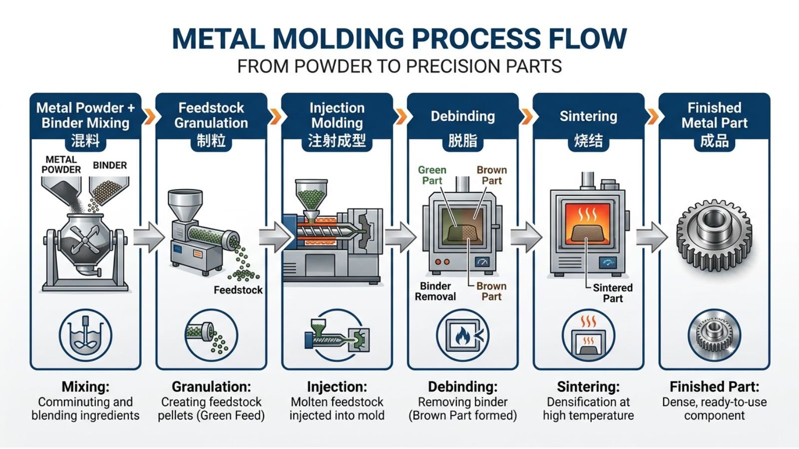
Figure 1: The four-stage Metal Injection Molding process for 17-4 PH stainless steel (Source: IQS Directory)
Stage 1: Feedstock and Powder Selection
Powder Atomization Method Matters
Your choice between gas-atomized and water-atomized powder significantly impacts final properties:
| Characteristic | Gas-Atomized | Water-Atomized |
|---|---|---|
| Particle Morphology | Highly spherical | Irregular |
| Oxygen Content | <500 ppm | >1000 ppm |
| Surface Cleanliness | Fewer inclusions | More oxide films |
| Cost | 30-50% premium | Standard |
| H900 UTS Achievement | 1200-1280 MPa | 1100-1150 MPa |
| Elongation (H900) | 8-9% | 6-7% |
Recommendation: For cost-sensitive, high-volume production with standard property requirements, water-atomized powder is adequate. For aerospace, medical, or maximum-performance applications, specify gas-atomized powder.
Particle Size Distribution
Typical specifications:
- Mean particle size: 10-16 µm
- -325 mesh fraction: 40-50%
- Finer powders(<10 µm mean): Enable lower sintering temperatures, higher final densities, better mechanical properties
- Trade-off: Finer powders increase material cost and can complicate powder handling
Stage 2: Molding - Designing for 15-20% Shrinkage
Critical Design Rule: Your mold cavity must be 18-20% oversized to compensate for sintering shrinkage.
Shrinkage Characteristics:
- Typical linear shrinkage: 15-20% depending on powder loading, sintering parameters
- Anisotropy: May vary 1-2% between X, Y, Z axes for complex geometries
- Predictability: Requires finite element modeling and empirical validation
Design Guidelines:
- Maintain uniform wall thickness where possible (1-3 mm optimal)
- Avoid thick sections (>6 mm) that resist uniform densification
- Transition gradually between thick and thin sections (avoid stress concentrators)
- Design in draft angles (0.5-1°) to facilitate part ejection
Stage 3: Debinding - The Hidden Critical Step
Debinding is where many MIM parts fail if not properly controlled. For 17-4 PH, the high sintering temperature provides some forgiveness, but defects created during debinding cannot be fully healed.
Common Defects from Poor Debinding:
- Blistering: Internal voids from gas trapped by too-rapid heating
- Cracking: Stress from uneven binder removal
- Surface defects: Carbon residue creating localized chemistry variations
- Slumping: Loss of dimensional control in thin sections
Process Control Requirements:
- Solvent debinding: Complete immersion, proper solvent purity
- Thermal debinding: Heating rate <2°C/min through critical range (200-450°C)
- Atmosphere: Inert or slightly reducing to prevent oxidation
- Time: Typically 24-48 hours for complete cycle
Stage 4: Sintering - Where Properties Are Born
Temperature and Atmosphere: The Critical Balance
For 17-4 PH, sintering typically occurs at 1300-1400°C in controlled atmosphere. Your choice of atmosphere profoundly affects final chemistry and properties.
Atmosphere Options:
| Atmosphere | Advantages | Disadvantages | Typical Results |
|---|---|---|---|
| High Vacuum (<10⁻² mbar) | Excellent oxide reduction, no gas contamination | High equipment cost, slower cycles | Best corrosion resistance |
| Partial H₂ (10-25% H₂ in N₂) | Good oxide reduction, faster cycles | Requires DEW point control | Good properties, cost-effective |
| Dissociated Ammonia | Very reducing, effective | Safety concerns, NH₃ handling | Excellent oxide reduction |
Oxygen and Carbon Control
This is where MIM becomes as much chemistry as it is mechanical processing:
Oxygen:
- Initial powder has 500-2000 ppm surface oxides
- Sintering atmosphere must reduce Cr₂O₃ back to metallic Cr
- Target final oxygen: <500 ppm for optimal properties
- High residual oxygen (>1000 ppm) ties up chromium, reducing both corrosion resistance and strength
Carbon:
- Source: Residual binder not fully removed during debinding
- Acts as reducing agent: C + Cr₂O₃ → 2Cr + CO↑
- Excess carbon (>0.15%) stabilizes austenite, reducing achievable hardness after aging
- Insufficient carbon means incomplete oxide reduction
- Target: 0.03-0.08% in final part
The Integrated System Approach
Successful MIM 17-4 PH production requires viewing binder chemistry, debinding cycle, and sintering atmosphere as a single integrated chemical system, not isolated process steps.
Video: Complete Metal Injection Molding manufacturing process from powder to finished part (MPIF)
✓ Key Takeaways: MIM Process for 17-4 PH
- Gas-atomized powder delivers 10-15% higher properties but costs 30-50% more
- Mold design must account for 15-20% shrinkage with potential anisotropy
- Debinding defects cannot be healed—this stage demands rigorous control
- Sintering atmosphere must both prevent oxidation AND reduce existing oxides
- Final O and C content critically affect properties; specify <500 ppm O, 0.03-0.08% C
Achievable Properties: Setting Realistic Expectations
One of the most critical aspects of designing with MIM 17-4 PH is understanding how properties compare to wrought material and where limitations exist.
Static Properties: Approaching Wrought Performance
As-Sintered State (Equivalent to Condition A):
- Density: 98-99% of theoretical (7.65-7.75 g/cm³)
- UTS: 800-950 MPa (wrought H1150: 931 MPa)
- Yield Strength: 650-750 MPa
- Elongation: 6-8%
- Hardness: 27-30 HRC
These properties are suitable for many applications without further heat treatment.
H900 Heat Treated (Maximum Strength):
- UTS: 1100-1280 MPa (wrought H900: 1310 MPa)
- Yield Strength: 950-1100 MPa (wrought H900: 1170 MPa)
- Elongation: 4-5% (wrought H900: 10%)
- Hardness: 38-42 HRC (wrought H900: 38-42 HRC)
Performance Assessment: MIM 17-4 PH achieves 85-95% of wrought static strength, with hardness matching wrought material. The primary difference is reduced ductility due to residual porosity.
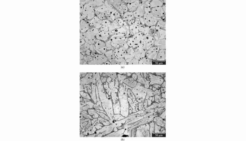
Figure 2: MIM 17-4 PH microstructure showing characteristic martensitic structure with controlled porosity (Source: ResearchGate Scientific Publication)
Dynamic Properties: The Critical Limitation
Fatigue Performance
The 1-2% residual porosity in MIM parts has disproportionate impact on fatigue life:
- MIM 17-4 PH H900 fatigue strength(10⁷ cycles): ~500 MPa
- Wrought 17-4 PH H900 fatigue strength(10⁷ cycles): ~750-850 MPa
- Performance ratio: 40-60% of wrought
Why the large difference?
- Residual pores act as pre-existing micro-notches
- Under cyclic loading, these pores are preferential fatigue crack initiation sites
- Crack propagates from pore much more readily than from smooth surface
Impact Toughness
V-notched Charpy impact tests show:
- MIM 17-4 PH: ~15% of wrought material impact energy
- Wrought 17-4 PH: Baseline reference
Under high-strain-rate loading, pores link up to provide easy crack propagation paths.
⚠️ Critical Design Implication
Youcannotsafely use wrought 17-4 PH fatigue data for MIM components. You must:
- Use MIM-specific fatigue datafrom your material supplier
- Apply appropriate safety factors(typically 1.5-2.0 for fatigue-loaded parts)
- Consider HIP post-processingif fatigue is critical (see below)
- Design to avoid stress concentrationsmore carefully than with wrought material
MIM vs. Wrought: Understanding the Performance Gap
The 1-2% residual porosity in MIM 17-4 PH creates a critical performance distinction from wrought material:
| Property Type | MIM Performance | Key Design Implication |
|---|---|---|
| Static Strength | 85-95% of wrought | Acceptable for most applications |
| Hardness | 100% match to wrought | Full equivalence achievable |
| Fatigue Strength | 40-60% of wrought | Must use MIM-specific data |
| Impact Toughness | ~15% of wrought | Avoid impact-critical applications |
Why the Difference?Residual pores act as stress concentrators under dynamic loading. While having minimal effect on static strength, they become preferential fatigue crack initiation sites and provide pathways for rapid crack propagation under impact.
Critical Design Rule: Never use wrought 17-4 PH fatigue data for MIM components. Always obtain MIM-specific S-N curves from your supplier and apply safety factors of 1.5-2.0× for fatigue applications.
Improving Properties: Hot Isostatic Pressing (HIP)
For applications where dynamic performance is critical, HIP post-processing can close remaining porosity:
HIP Process:
- Temperature: 1100-1150°C
- Pressure: 100-150 MPa isostatic gas pressure
- Duration: 2-4 hours
- Atmosphere: Argon
Results:
- Density increases to >99.5% (approaching 100%)
- Fatigue strength improves to 80-90% of wrought
- Impact toughness increases significantly
- Added cost varies by part size and geometry
When HIP makes sense:
- Flight-critical aerospace components
- High-cycle fatigue applications
- Safety-critical medical devices
- When part value justifies additional cost
✓ Key Takeaways: MIM 17-4 PH Properties
- Static strength approaches wrought (85-95%) with lower ductility
- Fatigue strength is 40-60% of wrought—use MIM-specific data
- Residual porosity is the limiting factor for dynamic properties
- HIP post-processing can achieve near-wrought dynamic performance
- Hardness fully matches wrought material across all heat treat conditions
Industrial Applications: Where MIM 17-4 PH Excels
Understanding successful applications helps you identify when MIM 17-4 PH is the optimal solution for your design challenge.
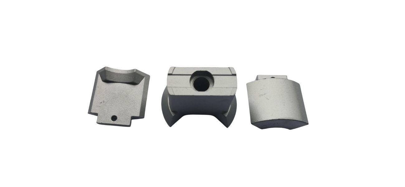
Figure 3: Real-world examples of MIM 17-4 PH components across industries (Source: ZCMIM)
Aerospace and Defense: High-Value, High-Complexity Parts
Typical Applications:
- Landing gear components (actuator housings, linkages)
- Turbine engine parts (nozzle guide vanes, lock wire fasteners)
- Flight control mechanisms
- Firearm components (grip safeties, trigger mechanisms, hammers)
- Missile and ordnance components
Case Study: Colt 1911 Grip Safety
This component exemplifies MIM 17-4 PH's value proposition:
Part Characteristics:
- Complex 3D curved geometry with ergonomic contours
- Multiple functional surfaces with tight relationships
- Production volume: 50,000+ units annually
- Previous process: Investment casting + extensive machining
MIM Benefits Realized:
- Cost reduction: Significant per-part cost decrease
- Lead time: Reduced compared to casting + machining
- Quality: Part-to-part consistency improved
- Machining: Most secondary operations eliminated
- Material waste: Reduced compared to machining
Property Requirements Met:
- Tensile strength: 1150 MPa (H900)
- Hardness: 38 HRC
- Corrosion resistance: Passes 72-hour salt spray
Medical and Dental: Precision with Biocompatibility
Typical Applications:
- Surgical instruments (laparoscopic tools, forceps, scissors)
- Orthodontic brackets
- Dental handpiece components
- Implantable device components (with appropriate surface treatment)
- Biopsy needles and cutting tools
Critical Success Factors:
1. Sharp Edges and Fine Features:
- MIM can produce cutting edges without secondary grinding
- Feature detail down to 0.2 mm possible
- Sharp internal corners achievable (unlike machining)
2. High-Volume Economics:
- Surgical instrument market requires 100,000+ units annually per design
- MIM's low per-part cost enables competitive pricing
- Consistent part-to-part quality critical for regulatory approval
3. Sterilization Resistance:
- 17-4 PH H900 withstands repeated autoclave cycles (134°C steam)
- Maintains hardness and corrosion resistance
- Surface finish (Ra <1 µm achievable) prevents bacterial colonization
Surface Treatment Requirements: For biocompatible applications:
- Electropolishing to Ra <0.3 µm
- Passivation to optimize Cr₂O₃ layer
- Biocompatibility testing per ISO 10993
Automotive and Industrial: Cost-Driven High Volume
Typical Applications:
- Turbocharger components (wastegate actuators, VGT mechanisms)
- Fuel injection system parts
- Transmission components (shift forks, sensor housings)
- Pump components for chemical processing
- Valve stems and seats for corrosive media
Value Drivers:
1. Part Consolidation: Example: Turbocharger actuator arm
- Previous design: 3 stamped parts + 2 + welding = 5 components
- MIM design: Single integrated part
- Assembly time eliminated, improved reliability
2. Volume Economics:
- Automotive production: 500,000+ vehicles/year
- Multiple parts per vehicle
- Low per-part cost achievable at scale
- Tooling cost amortized over multi-million part lifetime
3. Performance in Service:
- Operating temperatures to 300°C
- Exposure to fuels, oils, coolants
- 10+ year service life required
- Zero-defect quality expectations
Video: Advanced MIM technology demonstration showing precision manufacturing capabilities (Nymus 3D)
✓ Key Takeaways: Applications
- MIM 17-4 PH succeeds where complexity + volume + performance converge
- Medical/dental leverage fine features and sharp edges
- Aerospace/defense value part consolidation and weight reduction
- Automotive/industrial driven by cost at high volumes
- Surface finishing often required for biomedical or corrosion-critical applications
Critical Challenges and Practical Solutions
Success with MIM 17-4 PH requires anticipating common challenges and implementing proven mitigation strategies.
Challenge 1: Achieving Consistent Dimensional Accuracy
The Problem:
- 15-20% shrinkage during sintering
- Potential anisotropic shrinkage in complex geometries
- Batch-to-batch variation from powder or process drift
Solutions:
1. Characterize Shrinkage Empirically:
- Produce 30-50 sample parts from production tooling
- Measure actual shrinkage in X, Y, Z dimensions
- Document shrinkage variation (typically ±0.5%)
- Adjust tooling based on real data, not theoretical predictions
2. Design for Uniform Densification:
- Maintain consistent wall thickness (±20% variation maximum)
- Avoid thick sections (>6 mm) that densify differently
- Use gradual transitions (3:1 slope minimum) between sections
3. Statistical Process Control:
- Monitor key dimensions on every production batch
- Control powder lot-to-lot variation (particle size distribution)
- Maintain sintering furnace calibration (±10°C uniformity)
When to Machine After Sintering:
- Critical fits (bearings, seals): Machine after sintering to ±0.02 mm
- Non-critical features: Accept as-sintered ±0.3%
- Threads: Mold threads oversized, chase after sintering for critical applications
Challenge 2: Preventing Corrosion in As-Sintered Parts
The Problem: MIM 17-4 PH can exhibit pitting corrosion if:
- Chromium distribution is not homogeneous after sintering
- Residual porosity traps contaminants
- Surface chromium depleted by oxide formation
The Surface Chemistry Issue: During sintering, chromium preferentially oxidizes. Without proper atmosphere control:
- Surface chromium depleted from 15-17% to <12%
- Localized corrosion susceptibility increases
- Passive layer less protective than wrought material
Solutions:
1. Sintering Atmosphere Control:
- Use reducing atmosphere (H₂ or vacuum) throughout cooling
- Maintain dewpoint <-40°C to prevent water vapor oxidation
- Cool in protective atmosphere to <500°C before air exposure
2. Surface Finishing:
- Light Passivation: Citric or nitric acid bath restores Cr₂O₃ layer
- Electropolishing: Removes surface layer, exposes fresh high-Cr substrate
- Mechanical Polishing: To Ra <0.5 µm significantly improves pitting resistance
3. Testing and Validation:
- Salt spray testing (ASTM B117): Minimum 48 hours without red rust
- Cyclic corrosion testing for automotive applications
- Electrochemical potentiodynamic testing for critical applications
Practical Example: Medical instrument application required >200 hours salt spray resistance:
- As-sintered: Failed at 24 hours (pitting observed)
- After passivation: Passed 72 hours
- After electropolish + passivation: Passed >500 hours
Challenge 3: Managing Porosity-Related Property Variation
The Problem: Small variations in final density (98.0% vs 98.5%) cause disproportionate property variations, especially fatigue.
Root Causes:
- Powder lot variation in particle size distribution
- Sintering temperature variation (±20°C can affect density)
- Variations in green density from molding
- Incomplete debinding leaving carbon residue that affects densification
Solutions:
1. Powder Quality Control:
- Specify tight particle size distribution (±2 µm on D50)
- Require powder supplier certificates of analysis
- Test representative sample from each powder lot
2. Process Monitoring:
- Measure green density on statistical sample (target: >55% theoretical)
- Monitor sintering furnace with multiple thermocouples (±10°C max deviation)
- Track final density on every production batch (Archimedes method)
3. Acceptance Criteria: For critical applications, specify minimum density:
- Standard applications: >97.5% theoretical
- Structural applications: >98.0% theoretical
- Fatigue-critical applications: >98.5% theoretical OR specify HIP
Challenge 4: Delta-Ferrite Formation
The Problem: 17-4 PH can retain 5-15 vol% delta-ferrite in the final microstructure depending on cooling rate from sintering temperature.
What is Delta-Ferrite?
- High-temperature ferrite phase that doesn't fully transform to martensite
- Forms due to compositional inhomogeneity or insufficient cooling rate
- Appears as isolated "islands" in martensitic matrix
Effects on Properties:
- Positive: Slight improvement in ductility (ferrite is more ductile than martensite)
- Negative: Slight reduction in peak hardness and strength
- Magnetic properties: Affects magnetic permeability
- Generally benign: Research shows up to 10 vol% delta-ferrite does not impair UTS or elongation
When It Matters:
- Precise magnetic property requirements
- Maximum hardness applications (>40 HRC target)
- Aerospace specifications that limit delta-ferrite content
Control Methods:
- Increase cooling rate from sintering (>30°C/min if possible)
- Tighter composition control (especially Ni and Cr)
- Extended aging time to transform more ferrite to martensite
⚠️ Common Design Mistakes with MIM 17-4 PH
Mistake 1: Using Wrought Material Fatigue Data
- ✗Wrong: Designing for 750 MPa fatigue limit
- ✓Right: Use 500 MPa limit for MIM, or obtain supplier-specific data
Mistake 2: Specifying Unnecessary Tight Tolerances
- ✗Wrong: ±0.05% across entire part
- ✓Right: ±0.3% as-molded, machine only critical features to tighter tolerances
Mistake 3: Ignoring Shrinkage Anisotropy
- ✗Wrong: Assuming uniform 17% shrinkage in all directions
- ✓Right: Prototype first, measure actual shrinkage, adjust tooling
Mistake 4: Thick Section Design
- ✗Wrong: 10 mm thick boss in center of part
- ✓Right: Core out thick sections, maintain 1-4 mm walls with ribs for stiffness
Mistake 5: Assuming As-Sintered Corrosion Resistance Matches Wrought
- ✗Wrong: No surface treatment specified
- ✓Right: Specify passivation minimum, electropolish for demanding environments
Mistake 6: Underestimating Tooling Development Time
- ✗Wrong: Expecting production parts in 4 weeks
- ✓Right: Plan for 12-16 weeks: 8 weeks tooling + 4 weeks sampling + adjustments
Design Guidelines and Quick Decision Framework
Design Checklist for MIM 17-4 PH Parts
Before committing to MIM 17-4 PH, verify your design meets these criteria:
Volume and Economics:
- ☐ Annual production volume >10,000 units (or >5,000 for very complex parts)
- ☐ Part complexity justifies tooling investment
- ☐ Production will continue 3+ years to amortize tooling
Part Geometry:
- ☐ Part weight: 0.1-100g (optimal: 1-50g)
- ☐ Largest dimension: <100 mm
- ☐ Wall thickness: 0.5-6 mm (optimal: 1-3 mm)
- ☐ No features requiring side-pulls or complex tooling actions if possible
Property Requirements:
- ☐ Strength requirement: <1100 MPa (H900 achievable)
- ☐ If fatigue-critical: Willing to use MIM-specific data or add HIP
- ☐ Hardness requirement: <42 HRC achievable
- ☐ Elongation requirement: >4% if heat treated, >6% as-sintered
Application Requirements:
- ☐ Operating temperature: <300°C continuous
- ☐ Corrosion environment: Mild to moderate (with surface treatment)
- ☐ Surface finish: Ra <2 µm achievable, <0.5 µm with finishing
Tolerance Requirements:
- ☐ ±0.3% acceptable for non-critical dimensions
- ☐ Willing to add machining for critical features requiring ±0.05%
- ☐ Understand that shrinkage must be characterized and compensated
Quick Decision Framework: Is MIM 17-4 PH Right for Your Part?
Start Here → Production Volume
If <5,000 units/year:
- →MIM not economically viable- Tooling cost (which varies widely) cannot be amortized over small production volumes
- → Re-evaluate MIM when cumulative volume projections exceed 10,000 units
If 5,000-10,000 units/year (Borderline):
- → Highly complex geometry? → Yes →MIM may justify tooling investment
- → Simple geometry? → No →MIM advantage minimal, borderline case
- → Calculate break-even: Complex parts may justify at lower volumes (1,500-5,000)
If >10,000 units/year:
- → Part weight <100g? → No →MIM capabilities exceeded(sintering uniformity issues)
- → Part weight <100g? → Yes → Continue ↓
Geometric Complexity Assessment:
- → Multiple undercuts, internal features, complex 3D shape? → Yes →MIM strongly favored
- → Simple geometry achievable with 3-axis machining? → No →MIM advantage primarily volume-driven
Property Requirements:
- → Fatigue-critical cyclic loading? → Yes →Requires MIM-specific fatigue data or HIP post-processing
- → Static loading, <1100 MPa strength needed? → Yes →MIM 17-4 PH excellent choice
Final Decision:
- ✓ High volume + Complex geometry + Static loading =MIM 17-4 PH is optimal choice
- ⚠ High volume + Complex geometry + Fatigue loading =MIM 17-4 PH viable with HIP or design for MIM fatigue limits
- ✗ Low volume (<10,000) =MIM not economically justified regardless of geometry
- ✗ Simple geometry + standard volume =MIM advantage limited to volume economics only
- ✗ Part >100g or requires 100% density =MIM 17-4 PH not suitable
Looking for 17-4 PH MIM Powder?
Many engineers arrive at this topic while searching for a 17-4 PH MIM powder supplier or manufacturer. Here is the honest picture: MIM-grade 17-4 PH feedstock — gas-atomized powder, typically −22 µm, blended with a wax-polymer binder system — is produced by a small number of specialist feedstock suppliers, usually in 20 kg minimum lots, and buying it only makes sense if you operate your own molding, debinding, and sintering line.
If what you actually need is 17-4 PH components, the practical route is to buy the parts, not the powder. Emitech controls feedstock quality in-house: certified atomized powder, lot-traceable chemistry, and sintering cycles tuned to reach 99%+ density, delivering parts in H900–H1150 condition with full material certification — without feedstock procurement risk on your side. Send your drawing via our contact page for a quote, or see what we mold for firearms, medical, and industrial tool applications.
Frequently Asked Questions
Q: What density can I realistically expect from MIM 17-4 PH parts?
You should expect final densities of 98-99% of theoretical densitywith standard MIM processing. This translates to approximately 7.65-7.75 g/cm³ compared to 7.8 g/cm³ for fully dense wrought material. The residual 1-2% porosity consists of small (typically 5-20 µm), spherical pores distributed throughout the microstructure.
This porosity level has minimal impact on static tensile properties (10-15% reduction vs wrought) but significantly affects dynamic properties. If your application requires higher density for fatigue-critical service, Hot Isostatic Pressing (HIP) can close remaining porosity to achieve >99.5% density, bringing dynamic properties much closer to wrought levels.
Density Control: Work with your MIM supplier to establish minimum density acceptance criteria. For standard applications, >97.5% is typical. For structural or fatigue-loaded parts, specify >98.0% and verify through Archimedes testing on production samples.
Q: How do MIM 17-4 PH fatigue properties compare to wrought material?
MIM 17-4 PH fatigue strength is typically 40-60% of wrought material values. For H900 heat-treated condition:
- MIM fatigue strength(10⁷ cycles): ~500 MPa
- Wrought fatigue strength(10⁷ cycles): ~750-850 MPa
This significant difference stems from residual porosity acting as stress concentrators. Under cyclic loading, these microscopic pores become preferential sites for fatigue crack initiation.
Critical design implication: Youmust notuse wrought 17-4 PH fatigue data for MIM components. Instead:
- Request MIM-specific S-N curves from your supplier
- Apply conservative safety factors (1.5-2.0× for fatigue applications)
- Design to minimize stress concentrations more carefully than with wrought material
- For fatigue-critical applications (>10⁶ cycles), strongly consider HIP post-processing
HIP improvement: Hot Isostatic Pressing can increase fatigue strength to 80-90% of wrought levels by eliminating porosity that serves as crack initiation sites.
Q: What shrinkage should I expect during sintering, and how do I design for it?
Expect 15-20% uniform linear shrinkagefrom the green (molded) state to final sintered dimensions. This means:
- A final part dimension of 10.00 mm requires a mold cavity of approximately 11.8-12.0 mm
- Total volume shrinkage is approximately 40-50%
Shrinkage Characteristics:
- Generally uniform in all directions for simple geometries
- May exhibit slight anisotropy (1-2% difference between axes) in complex parts
- Depends on powder characteristics, feedstock formulation, and sintering parameters
Design Approach:
- Initial Tooling: Manufacturers use finite element analysis and empirical data to predict shrinkage within ±0.2%
- Validation: First article samples are measured to determine actual shrinkage
- Tooling Adjustment: Mold dimensions are adjusted based on real shrinkage data
- Production Control: Monitor key dimensions on every batch to detect drift
Pro Tip: For your first MIM project, budget for one tooling iteration to fine-tune dimensions. Experienced manufacturers can often hit targets on first try, but complex geometries may require adjustment.
Q: Can MIM 17-4 PH match wrought material corrosion resistance?
Yes, with proper processing and surface treatment, but the as-sintered condition may be inferior to wrought material.
The Challenge:
- During sintering, chromium preferentially oxidizes at the surface
- Residual porosity can trap contaminants and create crevice corrosion sites
- Non-uniform chromium distribution can create localized susceptibility
Achieving Wrought-Equivalent Performance:
- Sintering Atmosphere Control:
- Use reducing atmosphere (H₂ or vacuum) to prevent chromium depletion
- Maintain protective atmosphere during cooling to <500°C
- Surface Finishing(choose based on application severity):
- Passivation: Nitric or citric acid treatment restores Cr₂O₃ layer (minimum treatment)
- Electropolishing: Removes affected surface layer, exposes fresh high-Cr substrate
- Mechanical Polishing: To Ra <0.5 µm significantly improves pitting resistance
- Testing Validation:
- Salt spray (ASTM B117): Properly treated parts pass 72-200+ hours
- Comparable performance to wrought 17-4 PH and austenitic 304 SS in most environments
For Biomedical Applications: Electropolishing to Ra <0.3 µm followed by passivation is typically required to meet biocompatibility and corrosion requirements.
Q: What tolerances are achievable without secondary machining?
Standard MIM tolerances: ±0.3% of the nominal dimensionwithout secondary operations.
Examples:
- 10 mm dimension: ±0.03 mm (±30 µm)
- 50 mm dimension: ±0.15 mm (±150 µm)
- Flatness: ±0.1-0.2 mm per 25 mm
- Perpendicularity/parallelism: ±0.5°
Tighter tolerances possible with optimization:
- ±0.1-0.15%: Achievable with careful process control and favorable geometries
- ±0.05%or tighter: Requires post-sintering machining or grinding
Feature-Specific Tolerances:
- Holes: Can be molded ±0.3%; for critical fits (bearings, ), drill/ream after sintering
- Threads: Mold oversized threads, chase after sintering for critical applications
- Critical mating surfaces: Plan for light grinding or machining
Surface Finish:
- As-sintered: Ra 0.8–1.6 µm typical
- Tumbled/vibratory: Ra 0.4-0.8 µm
- Polished: Ra 0.2 µm achievable
Cost-Effective Strategy: Design to ±0.3% for most features, machine only critical surfaces that require tighter tolerances. This maximizes MIM's cost advantage while meeting performance requirements.
Q: How long does MIM 17-4 PH part development take from concept to production?
Typical Timeline: 12-16 weeks totalfrom concept to production.
Development Phase (8-12 weeks):
- Week 1-2: Design for manufacturability (DFM) review, tooling design
- Week 3-10: Mold fabrication (6-12 weeks depending on complexity)
- Week 11-12: First article sampling and dimensional validation
- Week 13-14(if needed): Tooling adjustment based on shrinkage data
- Week 15-16: Production validation and approval
Production Phase (4-8 weeks per batch once established):
- Molding: 1-3 days (depends on volume, cycle time 10-60 seconds per shot)
- Debinding: 1-3 days
- Sintering: 1-2 days
- Heat treatment: 1 day
- Inspection/finishing: 1-2 weeks
- Logistics: 1-2 weeks
Expedited Options: Some manufacturers offer rush services:
- Rapid tooling: 3-4 weeks
- Fast-track production: 2-3 weeks
- Premium pricing: Typically 30-100% surcharge
Planning Recommendations:
- For new product development: Start MIM tooling 4-6 months before production launch
- For design verification: Use CNC-machined prototypes while waiting for MIM tooling
- For critical time-to-market: Consider investment cast bridge production while MIM tools are developed
Q: What's the minimum order quantity and how does volume affect cost?
Initial production run typically requires 5,000-10,000 partsto justify tooling investment.
Minimum Order Quantities (varies by manufacturer):
- Initial production run: 5,000-10,000 parts to justify tooling investment
- Subsequent runs: 1,000-5,000 parts minimum
- Sample/prototype runs: 50-200 parts possible at premium pricing
Cost Structure:
| Cost Component | Range | Notes |
|---|---|---|
| Tooling | Varies | One-time investment, depends on complexity |
| Setup/Run | Varies | Per production batch |
| Material | Varies | Powder cost (17-4 PH) |
| Per-Part | Varies | Depends on size, volume, complexity |
Volume Economics Example(medium complexity part, 10g):
| Annual Volume | Amortized Tooling | Setup | Material+Process | Total Cost/Part |
|---|---|---|---|---|
| 5,000 | Varies | Varies | Varies | varies widely |
| 10,000 | Varies | Varies | Varies | varies widely |
| 50,000 | Varies | Varies | Varies | varies widely |
| 100,000 | Varies | Varies | Varies | varies widely |
Key Insight: Per-part cost drops dramatically with volume as tooling investment is amortized. The economic viability of MIM 17-4 PH is fundamentally volume-dependent.
For Low-Volume Requirements (<5,000 total lifecycle):
MIM 17-4 PH is typicallynot economically viabledue to high tooling costs that cannot be amortized over small production volumes. The economics work as follows:
- Tooling investment: varies widely (one-time)
- Cost per part at 5,000 units: high, driven largely by tooling amortization
- Total per-part cost: Often remains high even with processing included
At these volumes, the per-part cost remains prohibitively high despite MIM's processing efficiency. The break-even point for most parts occurs at 10,000-20,000 cumulative units, where tooling amortization becomes reasonable and MIM's low processing cost delivers economic advantage.
Exception: Extremely complex parts that would require extensive machining (8+ hours per part) may justify MIM tooling at lower volumes (1,500-3,000 units) because the alternative manufacturing cost is so high.
Q: Should I specify gas-atomized or water-atomized powder?
For most industrial applications, water-atomized powder provides adequate performanceat lower cost. Specifygas-atomized powderfor aerospace, medical, or applications requiring maximum properties.
Detailed Comparison:
| Factor | Gas-Atomized | Water-Atomized |
|---|---|---|
| Particle Shape | Highly spherical | Irregular |
| Oxygen Content | <500 ppm | >1000 ppm |
| Surface Quality | Cleaner, fewer inclusions | More oxide films |
| Material Cost | 30-50% premium | Baseline |
| H900 UTS | 1200-1280 MPa | 1100-1150 MPa |
| Elongation (H900) | 8-9% | 6-7% |
| Sintering | Lower temp possible | Standard temp required |
Decision Criteria:
Choose Gas-Atomized When:
- Maximum mechanical properties required (>1200 MPa UTS)
- Aerospace or medical applications with stringent requirements
- Ductility critical (need >7% elongation in H900)
- Customer specifications mandate it
- Part value justifies 30-50% material cost increase
Choose Water-Atomized When:
- Standard industrial applications
- Properties achievable: 1100-1150 MPa sufficient
- Cost optimization is priority
- High-volume consumer products
- 6-7% elongation acceptable
Practical Reality: Over 80% of MIM 17-4 PH production uses water-atomized powder. The property difference (10-15%) rarely justifies the cost premium for most applications.
Q: What heat treatment condition should I specify?
H900 is the most common choicefor MIM 17-4 PH, offering maximum strength, but selection depends on your application's priority.
Heat treatment selection depends on your application's priority: maximum strength, balanced properties, or maximum ductility.
Heat Treatment Selection Guide:
| Condition | When to Specify | Properties (MIM) | Typical Applications |
|---|---|---|---|
| As-Sintered | • Subsequent machining needed • Maximum ductility required • Cost-sensitive applications | UTS: 800-950 MPa YS: 650-750 MPa El: 6-8% HRC: 27-30 | Parts requiring post-MIM machining; non-critical structural |
| H900 (482°C) | • Maximum strength needed • Wear resistance critical • High hardness required | UTS: 1100-1280 MPa YS: 950-1100 MPa El: 4-5% HRC: 38-42 | Surgical instruments, firearm components, high-stress mechanical |
| H1025 (552°C) | • Balanced requirements • Moderate strength + toughness • Aerospace fasteners | UTS: 1000-1100 MPa YS: 900-1000 MPa El: 8-10% HRC: 33-38 | Aircraft fasteners, structural aerospace, defense |
| H1150 (621°C) | • Ductility priority • SCC resistance needed • Corrosive environment | UTS: 930-1000 MPa YS: 720-800 MPa El: 10-12% HRC: 28-32 | Chemical processing, marine, offshore |
Most Common Choice:H900accounts for approximately 70% of MIM 17-4 PH applications due to its excellent balance of high strength (>1100 MPa) and adequate ductility (4-5%).
Application-Specific Recommendations:
- Medical/Surgical: H900 for sharp edges and cutting tools
- Automotive: H900 for high-stress components, H1025 for balanced requirements
- Firearms: H900 for internal mechanisms requiring hardness
- Aerospace: H1025 for structural, H900 for non-structural high-strength
- Industrial: H900 standard unless ductility or SCC resistance drives H1150 selection
Pro Tip: Discuss application environment with your MIM supplier. They can recommend optimal heat treatment based on loading conditions, temperature exposure, and corrosive media.
Conclusion: Making the Right Decision for Your Application
17-4 PH stainless steel dominates the MIM industry because its precipitation-hardening metallurgy synergizes perfectly with the MIM thermal cycle. The high sintering temperature doubles as solution annealing, streamlining production and delivering components ready for simple, low-temperature aging to final properties.
When MIM 17-4 PH is Your Optimal Choice:
- High-volume production (>10,000 units annually) of complex, small-to-medium parts
- Strength requirements of 800-1280 MPa depending on heat treatment
- Good corrosion resistance comparable to wrought 17-4 PH and 304 SS
- Applications in medical, aerospace, firearms, automotive, or industrial sectors
- Need for part consolidation or features impossible with conventional manufacturing
Critical Success Factors:
- Understand that MIM properties approach but don't fully match wrought material
- Use MIM-specific data for fatigue-critical designs or add HIP post-processing
- Account for 15-20% shrinkage in tooling design
- Specify appropriate surface treatments for corrosion resistance
- Control powder quality, debinding, and sintering atmosphere as integrated system
The Economic Reality: MIM 17-4 PH delivers compelling economics only at sufficient volume to amortize tooling investment. For volumes below 5,000 units, CNC machining often remains more cost-effective despite material waste. But when your annual volume exceeds 10,000-20,000 units and part complexity is high, MIM can reduce per-part costs by 40-60% compared to machining.
Your Next Steps:
- Verify your design meets the criteria in our Design Checklist
- Use the Quick Decision Framework to assess MIM suitability
- Request quotes from 2-3 experienced MIM manufacturers
- Provide detailed application requirements (loading, environment, volume)
- Request MIM-specific material property data for your heat treatment condition
- Plan for 12-16 weeks development time from design to production parts
Success with MIM 17-4 PH requires understanding both the technology's remarkable capabilities and its inherent limitations. When applied to the right application—high volume, high complexity, and appropriate performance requirements—it delivers unmatched value. Make your decision based on comprehensive analysis of your component's lifecycle requirements using the frameworks provided in this guide.
Custom MIM Parts from Emitech
Nanjing Emitech delivers MIM 316L, 17-4PH, 4340 and other materials from tooling through sintering and finishing. Custom MIM parts · MIM services · Request a quote
Last updated: 2026-08-01