
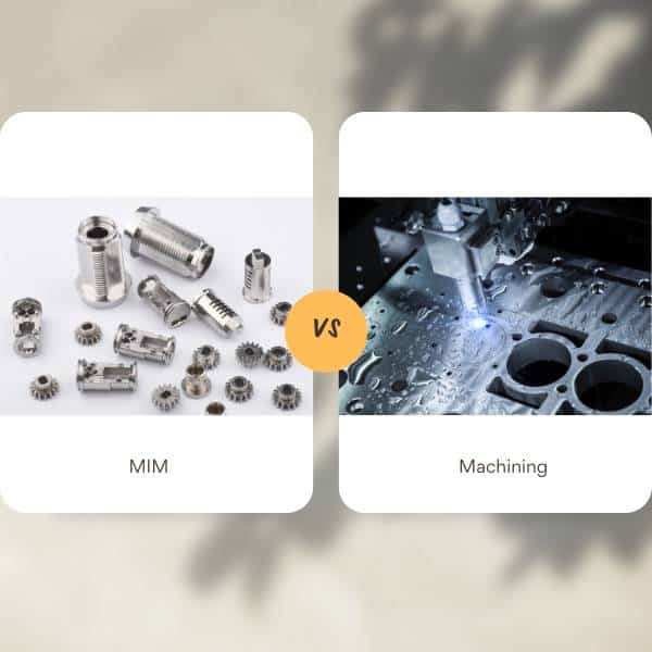
Metal Injection Molding (MIM) and CNC machining are complementary technologies. MIM typically offers lower per-part costs for high-volume, complex geometries, while CNC machining offers speed and precision without tooling investment. This guide provides the engineering framework to make that decision with confidence.
30-Second Decision Framework
Before diving into analysis, here are the clear-cut cases:
Choose MIM immediately if:
- Annual volume is high AND part has 3D complexity, undercuts, or cross-holes
- You're assembling 3+ machined components that could consolidate into one MIM part
- Part weight is 10-40g with geometry that requires 5-axis machining or multiple setups
- Material waste from machining exceeds 60% of the billet
Choose CNC immediately if:
- Production volume under 2,000 units annually
- Design changes expected quarterly or more frequently
- Application requires fatigue life >10^7 cycles with no budget for HIP post-processing
- You need parts in under 4 weeks
- Material is pure aluminum or copper (not MIM-compatible)
Requires detailed analysis if:
- Volume falls between 5,000-20,000 units annually
- Part has complex geometry but selective features need ±0.025mm tolerances (hybrid approach possible)
- You're working with expensive materials where waste becomes a significant cost factor
Understanding the Core Difference: Two Opposite Economic Models
The fundamental difference between MIM and machining isn't just technical—it's economic. These processes have opposite cost structures that determine when each makes sense.
Video: Metal Injection Molding process explained by Metal Powder Industries Federation (MPIF)
Metal Injection Molding: High Fixed Cost, Low Variable Cost
MIM combines powder metallurgy with injection molding. Fine metal powder (mixed with polymer binder) is injected into molds, then undergoes thermal processing to create dense metal parts.
Lead Time Impact:Multi-stage process (molding → debinding → sintering) requires several weeks for tooling and first articles. If you need parts in days, MIM is not an option.
Tolerance Characteristics:The part experiences 15-20% linear shrinkage during sintering. This shrinkage is predictable but variable, resulting in percentage-based tolerances (±0.3%).
Volume Economics:Once the tool is made, cycle time is fast and the process is highly automated. Cost per part drops as volume increases.
Economic Model:Total Cost = Tooling + (Per-Part Cost × Quantity). Tooling and per-part costs vary widely with part complexity, material, and cavitation. Request quotes for your specific geometry and volume.
CNC Machining: Low Fixed Cost, High Variable Cost
CNC machining removes material from solid metal blocks using computer-controlled cutting tools. You start with 100% dense wrought material and progressively remove everything that isn't your final part.
Lead Time Advantage:CAD to first part in days. No tooling investment required. Ideal for rapid prototyping and design iteration.
Tolerance Capability:Achieves absolute tolerances limited by machine accuracy. These tolerances don't scale with part size.
Complexity = Cost:Every feature adds machine time. Complex geometry with multiple setups can significantly increase per-part cost.
Economic Model:Total Cost = Setup + (Machine Time × Hourly Rate × Quantity). Setup and hourly rates vary with machine type, shop rate, and part complexity.
⚙️Decision Insight:MIM amortizes fixed costs over volume. CNC has minimal fixed costs but high variable costs. The crossover point is your break-even volume.
The Volume-Complexity Matrix: Your Primary Decision Tool
Geometric Capabilities: What Each Process Does Well
MIM's Geometric Strengths
MIM creates parts by flowing material into molds—similar to plastic injection molding. This enables geometric capabilities that are expensive or impossible to machine.
MIM excels at:
- 3D complex shapes with features on multiple planes
- Internal cavities and channels not accessible from outside
- Undercuts that would require multiple CNC setups or side-action molds
- Cross-holes at non-orthogonal angles
- Thin walls (<1.5mm) over significant areas
- Integrated features (threads, knurls, logos molded directly)
- Part consolidation (combining 3-5 machined components into one part)
Design constraint:MIM requires uniform wall thickness (typically 1-6mm). Thick sections must be cored out. Sharp internal corners must have generous radii. These are process requirements, not optional design preferences.
⚙️Decision Insight:The more features your part has that require multi-setup machining—undercuts, cross-holes, thin walls, complex 3D geometry—the stronger MIM's economic advantage. If your machinist quotes 5-axis machining or multiple setups, that's a signal MIM is worth evaluating.
CNC's Geometric Constraints
Every feature must be physically accessible by a cutting tool.
CNC limitations:
- Deep narrow pockets:Long slender tools vibrate and deflect, reducing accuracy
- Sharp internal corners:Rotating cutters always create radii. Smaller radius = smaller tool = slower cutting = higher cost
- Complex internal features:Standard milling cannot create curved internal channels—these require EDM, a specialized and expensive process
- Thin walls:Cutting forces cause deflection and vibration, resulting in poor accuracy and surface finish
Real scenario:You design a part with a sharp 90° internal corner. Your machinist explains: "I can give you a 3mm radius with a standard cutter, or 0.5mm radius with a micro-tool that breaks every 20 parts. Sharp corners require EDM." That design feature just became a significant cost driver.
⚙️Decision Insight:CNC favors simple prismatic shapes with features accessible from one or two directions. Every additional setup adds cost and potential error.
Complexity Assessment Scorecard
Score your part (1 point each):
- ☐ Features on multiple planes requiring multi-axis machining
- ☐ Internal cavities or channels not accessible from outside
- ☐ Undercuts requiring side-action molds or multiple setups
- ☐ Cross-holes at non-orthogonal angles
- ☐ Thin walls <1.5mm over significant areas
- ☐ Currently requires 2+ components to be assembled
- ☐ Integrated threads, knurls, or surface details
- ☐ High feature count (>20 distinct features)
Score interpretation:
- 0-2 points:Low complexity → CNC likely cost-effective even at moderate volumes
- 3-4 points:Moderate complexity → Volume-dependent; run break-even analysis
- 5-6 points:High complexity → MIM strong candidate at volumes >5,000
- 7-8 points:Very high complexity → MIM highly favored at volumes >2,000
Tolerances and Surface Finish
Dimensional Tolerances
MIM: Percentage-Based Tolerances
Standard: ±0.3% of dimension
| Feature Size | ±0.3% Tolerance |
|---|---|
| 10mm | ±0.030mm |
| 25mm | ±0.075mm |
| 50mm | ±0.150mm |
For small features (<25mm), MIM tolerances are quite tight. For larger features, they become progressively looser in absolute terms.
CNC: Absolute Tolerances
Standard: ±0.127mm | Precision: ±0.025mm | Ultra-precision: ±0.005mm
Tighter tolerances require additional operations (grinding, finishing passes), each adding 10-25% to part cost.
⚙️Decision Insight:For parts <40mm with standard tolerance requirements, MIM works well. For critical features requiring ±0.025mm absolute tolerance, plan for CNC or a hybrid approach (MIM + selective machining).
Surface Finish
MIM as-sintered: 0.8-1.2 µm Ra—smoother than standard CNC without finishing passes.
CNC standard: 3.2 µm Ra (tool marks visible).
CNC finished: 0.8 µm Ra (requires additional passes, adds 10-15% cost).
For consumer-facing products, MIM's as-produced finish can often eliminate separate polishing operations.
Material Selection and Performance Requirements
Material Availability
MIM-compatible materials:
- ✅ Stainless steels (316L, 17-4 PH, 304L, 420)
- ✅ Tool steels (M2, H13, D2)
- ✅ Titanium alloys (Ti-6Al-4V)
- ✅ Low-alloy steels
- ✅ Cobalt-chrome, tungsten alloys, copper alloys
NOT MIM-compatible:
- ❌ Pure aluminum (oxidation during sintering)
- ❌ Pure copper (excessive shrinkage)
- ❌ Magnesium alloys
The Density Question
MIM parts achieve 96-99% of theoretical density (1-4% microscopic porosity). CNC parts start from 100% dense wrought material.
| Property | MIM (96-99% Density) | CNC (100% Density) | Impact |
|---|---|---|---|
| Static strength | ✅ ~95-98% of wrought | ✅ Full wrought properties | Both adequate |
| Yield/tensile strength | ✅ Matches wrought after heat treatment | ✅ Full wrought properties | Both adequate |
| Fatigue strength | ⚠️ 15-20% lower than wrought | ✅ Full wrought fatigue life | CNC advantage |
| Impact toughness | ⚠️ 50-80% lower than wrought | ✅ Full wrought toughness | CNC advantage |
| Dimensional stability | ✅ Stress-free (superior long-term) | ⚠️ Residual stresses from cutting | MIM advantage |
When to choose CNC based on performance:
- High-cycle fatigue applications (>10^7 cycles): aircraft structures, high-speed rotating equipment
- Impact or shock loading: hand tools, mining equipment
- Mission-critical applications where failure is unacceptable
When MIM is adequate (85% of applications):
- Static or quasi-static loading
- Moderate fatigue life (<10^6 cycles)
- Consumer products, electronics, medical devices with moderate lifecycle
The HIP option:Hot Isostatic Pressing eliminates all porosity, bringing MIM parts to 100% density and full wrought properties. HIP adds cost per part.
⚙️Decision Insight:Don't assume you need 100% density. For most applications, MIM's 96-99% density delivers equivalent performance. Specify density based on actual failure modes, not "better is better" thinking.
Decision Framework: 8-Step Selection Process
Step 1: Production Volume Check
| Annual Volume | Action |
|---|---|
| <1,000 | Proceed with CNC; MIM not economical |
| 1,000-5,000 | CNC likely; run break-even if complexity is high |
| 5,000-20,000 | Detailed analysis required |
| >20,000 | MIM should be default choice unless geometry is very simple |
Step 2: Complexity Assessment
Use the 8-point scorecard above. Score 5+ = MIM strong candidate.
Step 3: Material Verification
Is your required material available for MIM? If no → CNC only.
Step 4: Performance Requirements
Is 100% density required due to high-cycle fatigue (>10^7 cycles), impact/shock loading, aerospace flight-critical classification, or customer specification?
Yes → CNC or MIM+HIP. No → MIM adequate.
Step 5: Tolerance Analysis
What percentage of features require ±0.025mm or tighter?
- <20% of features → Hybrid approach optimal
- >50% of features → Full CNC may be more economical
Step 6: Break-Even Calculation
Break-Even = MIM Tooling Cost ÷ (CNC Per-Part - MIM Per-Part)
- Your volume < break-even → Choose CNC
- Your volume > 2× break-even → Choose MIM
- Between 1× and 2× → Consider design stability and timeline
Step 7: Timeline Assessment
- Need parts in <4 weeks → CNC only
- Can accommodate 8-12 week tooling lead time → MIM viable
- Design changes expected quarterly → Favor CNC
- Design stable and validated → MIM investment justified
Step 8: Total Cost of Ownership
Calculate 3-5 year total including tooling (one-time for MIM), per-part cost, material waste, secondary operations, and assembly (if part consolidation is possible with MIM).
Strong CNC indicators (3+ apply):Volume <5,000 | Low complexity (score 0-2) | Material not MIM-compatible | >50% features need ±0.025mm | Frequent design changes expected
Strong MIM indicators (3+ apply):Volume >10,000 | High complexity (score 5+) | Part consolidation opportunity | Volume >2× break-even | Stable validated design | Product lifecycle >3 years
When Hybrid Makes Sense
The hybrid approach—MIM for near-net-shape plus selective CNC finishing—captures 70-85% of MIM's cost advantage while achieving specifications beyond standard MIM capability.
Ideal hybrid candidates:High volume (>10,000) justifying MIM tooling, complex overall geometry leveraging MIM's strengths, and selective features requiring ±0.025mm or tighter.
MIM + Bearing Surface Machining:MIM creates complex shape with 0.4mm stock on critical surfaces; CNC grinding finishes to ±0.01mm flatness. Added cost depends on feature size and tolerance. Applications: hinges, pivots, sliding components.
MIM + CNC Threading:MIM creates undersized pilot holes; CNC tapping creates precision threads with better quality and strength than molded threads. Added cost depends on hole size and quantity.
Common Misconceptions Debunked
Misconception 1: "MIM Parts Are Weaker"
For static loading, MIM achieves 95-99% of wrought strength. MIM vs. wrought 17-4 PH: yield strength 1,070-1,170 MPa vs. 1,170-1,240 MPa (91-100% equivalence); tensile strength 1,240-1,310 MPa vs. 1,310-1,380 MPa (95-99% equivalence).
Where it matters: high-cycle fatigue and impact loading, where 1-4% porosity reduces performance by 15-20% (fatigue) and 50-80% (impact). A defense contractor once rejected MIM citing "strength concerns"—after testing, MIM parts exceeded design loads by 3.5×, and the company switched to MIM, saving 68% per part.
Misconception 2: "MIM Can't Hold Tight Tolerances"
For small parts, MIM's percentage-based tolerance is actually tighter than standard CNC:
| Feature Size | MIM ±0.3% | CNC ±0.127mm | Winner |
|---|---|---|---|
| 10mm | ±0.030mm | ±0.127mm | MIM is 4× tighter |
| 25mm | ±0.075mm | ±0.127mm | MIM still tighter |
| 50mm | ±0.150mm | ±0.127mm | CNC tighter |
Misconception 3: "Machining Provides Better Surface Finish"
As-sintered MIM (0.8-1.2 µm Ra) is smoother than standard CNC (3.2 µm Ra). A consumer electronics company reduced finishing costs by switching to MIM's smoother as-sintered surface.
Misconception 4: "Design Changes Are Impossible with MIM"
Many modifications are feasible through mold modification:
Possible (typically thousands of dollars and weeks): dimensional adjustments, adding material to part, minor feature changes.
Requires new tooling: major geometry changes, significant size changes (>10%).
Strategy: prototype with CNC to validate design, then transition to MIM when stable.
Misconception 5: "CNC Provides Zero Waste"
CNC removes 50-80% of material as chips for complex parts. MIM uses 97%+ of material.
Example—50,000 titanium parts (45g each): CNC requires more starting billet; MIM uses feedstock more efficiently. The material savings can be substantial for expensive alloys.
Frequently Asked Questions
Q: At what volume does MIM become cost-effective?
There's no single answer—it depends on part complexity. Calculate your break-even: MIM Tooling ÷ (CNC Per-Part - MIM Per-Part).
General guidelines: simple parts break even at 20,000-50,000 units; moderate complexity at 10,000-20,000 units; high complexity requiring 5-axis CNC at 2,000-5,000 units. The more complex your geometry, the lower the break-even volume.
Q: Can MIM match machined part strength?
Static strength: yes, 95-99% equivalent. Dynamic properties (fatigue, impact): 15-20% lower due to 1-4% porosity.
MIM is adequate for 85% of applications involving static loading, moderate fatigue (<10^6 cycles), and predictable conditions. CNC is preferred for high-cycle fatigue (>10^7 cycles), impact loading, and mission-critical applications. HIP post-treatment achieves 100% density and full wrought properties at additional cost per part.
Q: What's the tightest MIM tolerance without machining?
±0.3% standard. For a 10mm dimension: ±0.030mm (comparable to standard CNC). For a 50mm dimension: ±0.150mm (looser than CNC). Use a hybrid approach for critical features requiring ±0.025mm while maintaining MIM's cost advantage on the rest of the part.
Q: Can I start with CNC and transition to MIM later?
Yes, and it's a proven strategy: design for MIM principles from the start (uniform walls, generous radii), prototype with CNC for 1-5,000 units, transition to MIM when volume justifies tooling and design is stable, then validate MIM parts against the machined baseline.
Critical: design for MIM initially. Don't optimize for machining then try to convert—the geometries are different.
Q: What materials can't be processed with MIM?
Pure aluminum (oxidation during sintering), pure copper (excessive shrinkage), and magnesium alloys cannot be processed. However, aluminum alloys and copper alloys are often MIM-compatible. For 90% of applications, required materials are available in both MIM and machined form.
Q: How much does MIM tooling cost and how long does it last?
Tooling cost depends on part complexity, cavitation, and material. Multi-cavity tools for complex geometries are significantly more expensive than simple single-cavity tools. With proper maintenance, tool life can run into hundreds of thousands or millions of shots, so the per-part tooling burden becomes small at high volumes.
Q: How do lead times compare?
CNC: 2-7 days to first parts, immediate design changes. MIM: 8-12 weeks to validated first articles, design changes require mold modification (typically thousands of dollars and weeks).
Timeline strategy: CNC for speed and design iteration; MIM for volume once design is frozen.
Conclusion
CNC machiningis the foundation of precision manufacturing: unmatched dimensional accuracy (±0.025mm standard), 100% material density, complete design flexibility without tooling investment, and 2-7 day turnaround. Optimal for prototypes, design iteration, low-to-medium volumes (1-10,000), mission-critical components, and materials not MIM-compatible.
Metal Injection Moldingdelivers transformative economics for high-volume complex parts: significant cost savings over machining at appropriate volumes, geometric freedom for 3D complexity and undercuts, part consolidation, and excellent as-produced surface finish. Optimal for higher volumes, complex geometries, small-to-medium parts, and stable validated designs.
Hybrid approachcaptures the advantages of both: MIM creates complex near-net-shape (70-85% cost savings vs. full CNC), selective machining achieves tight tolerances where needed.
Volume is your primary factor:<5,000 units → default to CNC. 5,000-20,000 units → detailed analysis. >20,000 units → MIM typically optimal for any significant complexity.
Geometric complexity determines break-even:simple parts need higher volumes to justify MIM; complex parts break even at surprisingly low volumes. Use the 8-point complexity scorecard.
Your action plan for new products:
- Design for MIM principles from the start
- Prototype with CNC (1-1,000 units)
- Run break-even analysis when volume projections solidify
- Transition to MIM when volume exceeds 2× break-even
- Validate MIM parts against baseline before full production
Engage manufacturing partners early in design. Engineers experienced in both MIM and CNC can guide decisions that optimize manufacturability, avoiding costly redesigns later.
Precision Metal Parts from Emitech
Nanjing Emitech delivers MIM, CNC machining, and custom metal parts. MIM services · Request a quote
Last updated: 2026-06-24
Continue reading
- MIM vs Sintering: Understanding the Difference (One Is Part of the Other)
- MIM's External and Internal Undercut Design: Complex, Cheap, and Fixing Production Issues
- Oil Impregnated Bronze Bushings: The Complete Guide for Engineers and Buyers
- How P.A.N.A.C.E.A. Stainless Steel Performs in MIM Sintering: An In-Depth Technical Analysis