
Your sintered P.A.N.A.C.E.A. parts are failing magnetic permeability specs, and you're facing rejection rates you've never seen with 316L. The nitrogen-manganese stabilization system requires fundamentally different sintering protocols where your furnace atmosphere actively determines final composition.
Why P.A.N.A.C.E.A. Sintering Is Different
P.A.N.A.C.E.A. (Protection Against Nickel Allergy, Corrosion, Erosion, and Abrasion), designated as X15 CrMnMoN 17-11-3 under European standards, isn't a nickel-free variant of 316L—it's a distinct alloy system where sintering behavior diverges fundamentally from conventional MIM steels.
The Metallurgical Challenge: Volatile and Gaseous Stabilizers
Traditional austenitic steels like 316L use nickel (10-14%) to stabilize the face-centered cubic (FCC) austenite structure. Nickel is stable at sintering temperatures—your final composition matches your starting powder chemistry.
P.A.N.A.C.E.A. replaces nickel with two elements that create complex sintering challenges:
Manganese (10.5-12.0%): Your primary austenite stabilizer, but manganese exhibits significant vapor pressure above 700°C, reaching approximately 10⁻³ Pa at this threshold. At typical sintering temperatures of 1250-1380°C, manganese sublimation becomes the dominant process challenge. Lose too much manganese from the surface, and your austenite transforms to magnetic δ-ferrite.
Nitrogen (0.15-0.90%): Approximately eighteen times more effective than nickel at stabilizing austenite on a weight basis. Nitrogen also provides powerful solid-solution strengthening by occupying interstitial sites in the FCC lattice, creating lattice distortions that impede dislocation movement. However, as a gaseous element, your final nitrogen content isn't determined by powder chemistry alone—it's actively controlled by furnace atmosphere composition and partial pressure during sintering.
Critical Implication: Your sintering atmosphere isn't protective—it's reactive. The furnace becomes a chemical reactor where gas-solid equilibria determine whether you produce non-magnetic components with UTS >1090 MPa or magnetic scrap with failed specifications.
Table 1: Composition Comparison Highlighting Sintering Challenges (wt.%)
| Element | P.A.N.A.C.E.A. | 316L | Sintering Behavior Impact |
|---|---|---|---|
| Manganese (Mn) | 10.5-12.0 | ≤2.00 | Sublimates >700°C; requires pressure control |
| Nitrogen (N) | 0.15-0.90 | ≤0.10 | Atmosphere-dependent; controls phase stability |
| Nickel (Ni) | ≤0.10 | 10.0-14.0 | Ni stable; Mn/N volatile/reactive |
| Chromium (Cr) | 16.5-17.5 | 16.0-18.0 | Forms Cr₂N if cooled slowly |
| Molybdenum (Mo) | 3.0-3.5 | 2.00-3.00 | Stable during sintering |
Powder Requirements for Successful Sintering
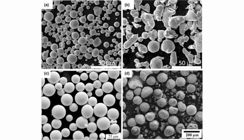
Your powder production method directly determines sintering success. Water atomization—standard for commodity steels—creates a highly oxidizing environment that forms stable manganese oxides on particle surfaces. These oxides resist reduction during sintering, creating barriers to inter-particle bonding that prevent densification.
Why Inert Gas Atomization Is Mandatory
P.A.N.A.C.E.A. powder must be produced via inert gas atomization (IGA), where molten alloy is disintegrated by high-velocity argon or nitrogen jets:
- Prevents manganese oxidation: Inert atmosphere shields reactive elements during solidification
- Controls nitrogen content: Using nitrogen as atomizing gas maintains or enriches powder nitrogen levels
- Creates spherical morphology: Enables high powder loading (~60 vol%), minimizing binder volume and sintering shrinkage
- Delivers low oxygen: <0.2% oxygen prevents oxide barriers to densification
Critical Powder Specifications for Sintering Performance:
- D₅₀ (median): 10.5-13.0 μm (high surface area for sintering kinetics)
- D₉₀: <22 μm (maintains feedstock rheology)
- Morphology: Spherical (enables high packing density)
- Oxygen: <0.2% (prevents oxide formation during sintering)
The Sintering Cycle: Where Composition and Microstructure Are Determined
Your P.A.N.A.C.E.A. sintering cycle is precision thermo-chemical processing where every parameter interacts to determine final properties.
Thermal Profile: Balancing Densification Against Manganese Loss
Stage 1: Controlled Heating
- Rate: 5 K/min to 600°C
- Objective: Prevent thermal shock; control binder decomposition
Stage 2: Binder Burnout
- Hold: 60 minutes at 600°C
- Critical: Incomplete binder removal causes porosity and carbon contamination
Stage 3: Ramp to Sintering Temperature
- Rate: 5 K/min to 1250-1380°C
- Trade-off: Higher temperatures accelerate densification but exponentially increase manganese sublimation
Stage 4: Sintering Hold
- Duration: 60-120 minutes
- Mechanisms: Grain boundary diffusion, surface diffusion, lattice diffusion eliminate porosity
- Critical balance: Each additional minute improves densification but increases cumulative manganese loss
Atmospheric Control: Engineering Final Nitrogen Content
Unlike 316L where atmosphere prevents oxidation, your P.A.N.A.C.E.A. atmosphere actively controls final composition through gas-solid equilibria.
Two Primary Strategies:
Option 1: Mixed Gas Atmosphere
- Composition: 75% N₂ / 25% H₂
- Pressure: ~1000 mbar
- H₂ function: Reduces surface oxides
- N₂ function: Controls nitrogen absorption/retention
Option 2: Pure Nitrogen Atmosphere
- Composition: 100% N₂
- Pressure: 800 mbar
- Objective: Precise nitrogen partial pressure control
The Critical Nitrogen Partial Pressure-Property Relationship
Your nitrogen partial pressure during sintering directly determines whether parts meet specifications:
Insufficient N₂ Partial Pressure (<60 kPa):
- Final nitrogen: ~0.56%
- Magnetic permeability (μᵣₑₗ): ~1.01 (marginal—fails specification)
- Microstructure: Incomplete austenite stabilization
- Result: Magnetic parts, specification failure
Optimal N₂ Partial Pressure (>80 kPa):
- Final nitrogen: ≥0.68%
- Magnetic permeability: <1.002 (fully non-magnetic)
- Microstructure: Fully austenitic FCC structure
- Result: Non-magnetic parts with superior strength
This relationship is your most powerful process control lever, but requires specialized furnace capabilities: precise gas mixing, high-purity handling, and accurate partial pressure monitoring throughout the cycle.
Mandatory Rapid Cooling: Kinetic Microstructure Trapping
You must achieve cooling rates exceeding 150°C/min from sintering temperature via high-pressure inert gas quenching. This rapid quench isn't for hardening—it's kinetically trapping a metastable microstructure.
Two Critical Objectives:
1. Suppress Chromium Nitride (Cr₂N) Precipitation
At sintering temperature (~1300°C), nitrogen is held in supersaturated solid solution. During slow cooling, decreasing nitrogen solubility drives Cr₂N precipitation at grain boundaries. Each precipitate creates a chromium-depleted zone in the adjacent matrix. These depleted zones cannot maintain the passive oxide layer—they corrode preferentially, destroying the alloy's corrosion resistance advantage over 316L.
Rapid cooling kinetically suppresses precipitation by bypassing the critical temperature range too quickly for diffusion-controlled Cr₂N formation.
2. Prevent δ-Ferrite Formation
If any manganese loss occurred during sintering, slow cooling allows transformation from non-magnetic FCC austenite to magnetic BCC δ-ferrite. Even small amounts cause magnetic property failures. Rapid cooling preserves the high-temperature austenitic structure.
Section Thickness Limitation: Thick sections (>10-15 mm) cool more slowly in their core. If core cooling rate falls below 150°C/min, you'll experience Cr₂N precipitation or δ-ferrite formation internally, even if surface microstructure is acceptable. This imposes practical geometry constraints not encountered with thermodynamically stable alloys like 316L.
Table 2: Critical Sintering Parameters
| Parameter | Specification | Sintering Impact |
|---|---|---|
| Peak Temperature | 1250-1380°C | Balance densification vs. Mn sublimation |
| Atmosphere | 75% N₂/25% H₂ or 100% N₂ | Determines final N content |
| N₂ Partial Pressure | >80 kPa | Ensures non-magnetic properties |
| Hold Time | 60-120 min | Complete densification; minimize duration |
| Cooling Rate | >150°C/min | Prevents Cr₂N and δ-ferrite |
Microstructural Development During Sintering
Target: Metastable Austenitic Structure
Your objective is a single-phase austenitic microstructure:
- Crystal structure: Face-centered cubic (FCC)
- Nitrogen state: Supersaturated interstitial solid solution
- Grain structure: Equiaxed austenitic grains
- Residual porosity: ~3% (small, isolated, spherical pores)
- Undesirable phases: None (no δ-ferrite, no Cr₂N)
This metastable structure—not thermodynamically stable at room temperature—delivers the property combination: UTS ≥1090 MPa, elongation ≥35%, μᵣₑₗ <1.01.
Sintering Failure Mode 1: δ-Ferrite from Manganese Depletion
Mechanism: Excessive manganese sublimation during sintering reduces austenite stabilizer concentration below the critical threshold. Upon cooling, surface regions transform to ferromagnetic BCC δ-ferrite.
Detection: Magnetic permeability μᵣₑₗ >1.01; EBSD analysis reveals ferrite at surfaces
Root Causes:
- Insufficient furnace pressure (low pressure exacerbates Mn sublimation)
- Excessive peak temperature or hold time
- Inadequate nitrogen partial pressure
- Poor atmosphere flow (Mn-rich vapor accumulation)
Process Corrections:
- Increase operating pressure to suppress Mn vapor gradient
- Reduce peak temperature or shorten hold time
- Increase N₂ partial pressure >80 kPa
- Optimize atmosphere flow patterns
Sintering Failure Mode 2: Cr₂N Precipitation from Slow Cooling
Mechanism: Insufficient cooling rate allows Cr₂N precipitation during temperature reduction. Chromium-depleted zones adjacent to precipitates corrode preferentially, undermining corrosion resistance.
Detection: Localized corrosion in service; metallography reveals grain boundary precipitates; EPMA confirms Cr-depleted halos
Root Causes:
- Cooling rate <150°C/min
- Thick sections cooling slowly in core
- Inadequate quench system capacity
Process Corrections:
- Verify >150°C/min throughout cross-section
- Implement maximum section thickness limits (10-15 mm)
- Upgrade quench system capacity
- Consider post-sinter solution anneal (1040-1100°C) + second quench for thick sections
Surface Microstructure: Dense Layer Phenomenon
Sintered P.A.N.A.C.E.A. typically develops a highly dense surface layer (~200-300 μm thick) with higher residual porosity in the core. This gradient results from direct surface interaction with reactive nitrogen atmosphere, enhancing surface diffusion and densification.
Sintering Process Implication: For components requiring deep polishing (watch cases, jewelry), aggressive material removal that penetrates this dense layer exposes porous subsurface, creating visible pitting. Solution: optimize nitrogen partial pressure profile during sintering for more uniform through-thickness densification, or limit polishing depth specifications.
Properties Achieved Through Optimized Sintering
Successful sintering produces these properties in the as-sintered and quenched condition:
Mechanical Properties:
- Ultimate Tensile Strength: ≥1090 MPa (>2× sintered 316L)
- Yield Strength: ≥690 MPa
- Hardness: 270-300 HV10
- Elongation: ≥35% (high strength without brittleness)
- Density: ≥7.50 g/cm³ (97% theoretical)
Physical Properties:
- Magnetic permeability: μᵣₑₗ <1.01 (non-magnetic when properly sintered)
- Corrosion resistance: 25% superior to 316L (ASTM B117 salt spray: 0.003% vs 0.018% weight loss)
Critical Understanding: These properties aren't inherent to the alloy chemistry—they're the direct outcome of proper sintering process control. Inadequate nitrogen partial pressure, excessive manganese loss, or insufficient cooling rate produces parts that fail specifications despite starting with correct powder chemistry.
Table 3: Sintering Process Impact on Final Properties
| Property | Properly Sintered | Poor Sintering | Cause of Degradation |
|---|---|---|---|
| Tensile Strength | ≥1090 MPa | <900 MPa | Low final N content |
| Magnetic Permeability | <1.002 | >1.01 | Mn loss → δ-ferrite |
| Corrosion Resistance | Excellent | Poor | Cr₂N precipitation |
| Elongation | ≥35% | <25% | High porosity from poor densification |
Why 316L Sintering Protocols Fail for P.A.N.A.C.E.A.
Understanding why conventional sintering approaches fail clarifies P.A.N.A.C.E.A.'s unique requirements.
P.A.N.A.C.E.A. vs. 316L Sintering Comparison
Atmosphere Function:
- 316L: Protective (H₂, Ar, or vacuum prevents oxidation)
- P.A.N.A.C.E.A.: Reactive (N₂ atmosphere determines final composition)
- Consequence: Sintering P.A.N.A.C.E.A. in 316L atmosphere causes nitrogen loss, destroyed austenite stability, magnetic parts
Temperature Strategy:
- 316L: 1320-1375°C (maximize densification; austenite thermodynamically stable)
- P.A.N.A.C.E.A.: 1250-1380°C (constrained by Mn sublimation; narrow optimization window)
Cooling Requirements:
- 316L: Slow cooling acceptable (stable austenite)
- P.A.N.A.C.E.A.: Mandatory >150°C/min quench (trap metastable structure)
Microstructural Stability:
- 316L: Thermodynamically stable austenite (robust, forgiving)
- P.A.N.A.C.E.A.: Metastable supersaturated solid solution (sensitive to deviations)
P.A.N.A.C.E.A. vs. 17-4PH: Opposite Requirements
Atmosphere:
- P.A.N.A.C.E.A.: Nitrogen-rich mandatory
- 17-4PH: Nitrogen actively avoided (prevents martensitic transformation needed for hardening)
Cooling Objectives:
- P.A.N.A.C.E.A.: Rapid quench preserves austenite
- 17-4PH: Controlled cooling forms martensite for subsequent aging
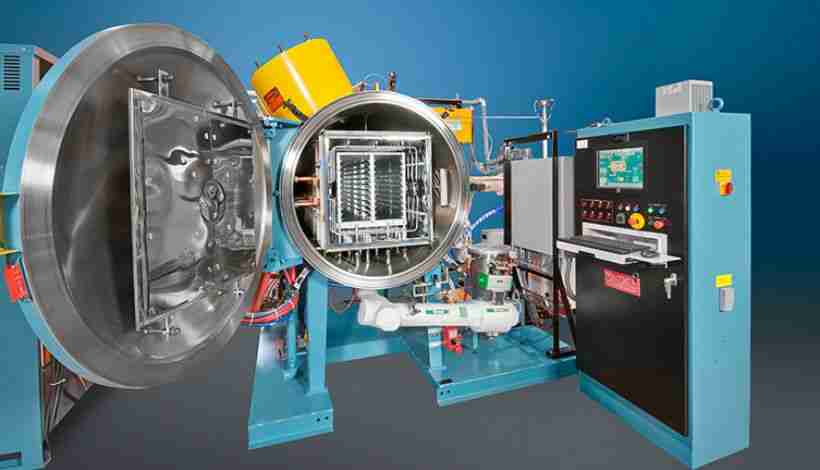
Equipment Implications: These mutually exclusive requirements mean you cannot simply reprogram existing furnaces. P.A.N.A.C.E.A. requires dedicated equipment with nitrogen gas systems, partial pressure control, and high-pressure quenching capability.
Table 4: Sintering Protocol Comparison
| Parameter | P.A.N.A.C.E.A. | 316L | 17-4PH |
|---|---|---|---|
| Atmosphere Function | Reactive/Compositional | Protective | Protective |
| Gas Composition | 75% N₂/25% H₂ or pure N₂ | Pure H₂, Ar, or Vacuum | Pure H₂ or Vacuum |
| Cooling Requirement | >150°C/min quench | Slow cooling acceptable | Controlled to form martensite |
| Microstructure Goal | Preserve metastable austenite | Stable austenite | Form martensite |
| Post-Sinter Treatment | None required | None | Aging (e.g., H900 at 480°C) |
Manufacturing Process Control for Consistent Sintering
Dimensional Control: Managing Sintering Shrinkage
Linear sintering shrinkage: 15-20% (specific value depends on powder loading, peak temperature, hold time, final density)
Anisotropic Shrinkage: Parts often shrink at different rates along different axes due to particle orientation during molding and gravitational effects during sintering. You must characterize axis-specific shrinkage for each geometry and compensate in mold design.
Achievable Tolerances:
- General: ±0.3-0.5% of dimension
- Optimized: ±0.025 mm for dimensions <3 mm
- Minimum wall thickness: ~0.3 mm
Critical Process Control Points
1. Manganese Retention Management
Furnace Pressure: Maintain stable high pressure throughout hot zone; higher pressure suppresses Mn sublimation
Thermal Cycle: Minimize time-at-temperature >1250°C; reduce hold time to minimum achieving target density
Atmosphere Flow: Adequate gas velocity removes sublimated Mn vapor; prevents localized composition variations
Component Loading: Account for surface-to-volume ratio; thin walls more susceptible to Mn loss
2. Nitrogen Homogeneity
Furnace Design: Controlled gas flow preventing dead zones; uniform temperature throughout hot zone
Process Monitoring: Part-to-part consistency within batches indicates uniform atmosphere; position-dependent property variations suggest atmosphere gradients
3. Cooling Rate Achievement
Section Thickness: Verify >150°C/min through entire cross-section; implement maximum thickness limits (10-15 mm) based on quench capability
Quench System: Monitor gas flow rates and pressure; degraded performance compromises properties
Quality Assurance: Verifying Sintering Success
Chemical Composition:
- Final nitrogen: 0.60-0.70% (correlates with non-magnetic properties)
- Manganese retention: Within specification limits
- Frequency: Batch validation minimum
Metallographic Examination:
- SEM/EBSD: Confirm fully austenitic structure; screen for δ-ferrite
- EPMA: Elemental mapping detects Mn depletion, Cr-depleted zones
- Porosity quantification: ~3% residual typical
Magnetic Permeability:
- Measure on production components (not just test coupons)
- Specification: μᵣₑₗ <1.01
- Statistical process control: Monitor trends indicating process drift
Mechanical Testing:
- Tensile: UTS ≥1090 MPa, YS ≥690 MPa, elongation ≥35%
- Hardness: 270-300 HV10
Troubleshooting Sintering Problems
Problem: Magnetic Parts (μᵣₑₗ >1.01)
Root Causes:
- Excessive manganese sublimation → δ-ferrite formation
- Insufficient nitrogen partial pressure (<60 kPa)
- Peak temperature too high or hold time too long
Solutions:
- Increase furnace operating pressure
- Increase N₂ partial pressure to >80 kPa
- Reduce peak temperature or shorten hold time
- Verify uniform atmosphere distribution
Validation: Re-measure magnetic permeability; EBSD confirms elimination of δ-ferrite
Problem: Poor Corrosion Resistance
Root Causes:
- Cr₂N precipitation from cooling rate <150°C/min
- Thick sections cooling slowly in core
- Inadequate quench system performance
Solutions:
- Verify cooling rate >150°C/min throughout cross-section
- Upgrade quench system capacity
- Implement section thickness design limits
- Consider post-sinter solution anneal (1040-1100°C) + second quench
Validation: Metallography for Cr₂N precipitates; EPMA for Cr-depleted zones; corrosion testing
Problem: Low Strength (UTS <1000 MPa)
Root Causes:
- Insufficient final nitrogen content
- Inadequate densification (high residual porosity)
- Incorrect thermal cycle
Solutions:
- Increase nitrogen partial pressure during sintering
- Chemical analysis: verify nitrogen content 0.60-0.70%
- Optimize temperature-time profile for densification
- Check powder quality and feedstock formulation
Validation: Density measurement (≥7.50 g/cm³); nitrogen analysis; porosity quantification
Problem: Dimensional Variation
Root Causes:
- Feedstock inconsistency (powder loading variation)
- Furnace thermal/atmospheric non-uniformity
- Anisotropic shrinkage not compensated
Solutions:
- Verify feedstock mixing consistency
- Furnace uniformity mapping studies
- Characterize axis-specific shrinkage
- Adjust mold dimensions with directional compensation
Validation: Statistical process control on dimensions; furnace characterization; shrinkage mapping
Frequently Asked Questions
Q: What nitrogen partial pressure should I target during sintering?
A: Target >80 kPa nitrogen partial pressure to ensure non-magnetic properties. Below 60 kPa produces final nitrogen content ~0.56% with magnetic permeability ~1.01 (specification failure). Above 80 kPa achieves final nitrogen ≥0.68% with fully non-magnetic properties (μᵣₑₗ<1.002). This requires precise gas mixing and partial pressure monitoring throughout the cycle—standard protective atmosphere control is insufficient.Q: Why is >150°C/min cooling mandatory?
A: The rapid cooling requirement kinetically traps a metastable microstructure. Slow cooling allows two detrimental transformations: (1) chromium nitride precipitation that depletes the matrix of chromium and destroys corrosion resistance, and (2) potential δ-ferrite formation resulting in magnetic properties. Rapid cooling bypasses the temperature range where these diffusion-controlled reactions occur, preserving the desired supersaturated austenitic structure.
Q: Can I sinter P.A.N.A.C.E.A. in my 316L furnace?
A: No—P.A.N.A.C.E.A. requires a nitrogen-containing atmosphere while 316L uses protective hydrogen, argon, or vacuum. Your furnace needs: (1) a nitrogen gas supply with precise partial pressure control (>80 kPa), (2) high-pressure gas quenching achieving >150°C/min cooling, and (3) modified atmosphere handling. Most facilities require dedicated equipment due to mutually exclusive processing conditions.
Q: How do I prevent manganese loss during sintering?
A: Minimize manganese sublimation through: (1) high furnace operating pressure (suppresses vapor pressure gradient), (2) optimized thermal cycle (minimize time >1250°C, use shortest hold time achieving adequate densification), (3) proper atmosphere flow (removes sublimated Mn vapor), and (4) consideration of component surface-to-volume ratio (thin walls are more susceptible).
Q: What is the maximum section thickness for P.A.N.A.C.E.A.?
A: The practical maximum is 10-15 mm due to the >150°C/min cooling requirement. Thick sections cool more slowly in their core, potentially causing Cr₂N precipitation or incomplete austenite retention internally even if the surface is acceptable. For thicker sections: perform thermal modeling of cooling rates, implement destructive testing to verify core microstructure, or consider post-sinter solution annealing (1040-1100°C) followed by a second rapid quench.
Q: Why do polished parts show pitting after finishing?
A: Sintered P.A.N.A.C.E.A. develops a dense surface layer (~200-300 μm) with a more porous core—a gradient from the reactive nitrogen atmosphere enhancing surface densification. Aggressive polishing removing this layer exposes the porous subsurface, creating visible pitting. Solutions: (1) limit polishing depth to remain within the dense surface zone, (2) optimize sintering parameters for more uniform through-thickness densification, or (3) coordinate polishing specifications with the measured dense layer thickness.
Q: Does P.A.N.A.C.E.A. require post-sintering heat treatment?
A: No—P.A.N.A.C.E.A. achieves final properties (UTS ≥1090 MPa, YS ≥690 MPa) directly from the sinter-and-quench cycle without secondary aging like 17-4PH requires. However, optional post-sinter solution annealing (1040-1100°C) followed by rapid quench may benefit applications requiring absolute microstructural uniformity—particularly thick sections where initial quench may not fully suppress core precipitation.
Q: How does sintering atmosphere affect final properties?
A: The sintering atmosphere directly controls final nitrogen content through gas-solid equilibria, which determines phase stability and properties. Nitrogen partial pressure >80 kPa produces final nitrogen ≥0.68%, resulting in a fully austenitic non-magnetic structure (μᵣₑₗ<1.002) with superior strength. Insufficient nitrogen partial pressure (<60 kPa) produces only 0.56% nitrogen with marginal magnetic properties (μᵣₑₗ ~1.01) and lower strength. This makes atmosphere control your most powerful process lever.
Conclusion: Sintering Process Mastery Determines Success
P.A.N.A.C.E.A. sintering performance depends entirely on recognizing that you're implementing a fundamentally different metallurgical process than conventional MIM steels. Your furnace atmosphere isn't protective—it's reactive, actively determining final composition. Your cooling isn't conventional—it's kinetic microstructure trapping, preserving a metastable structure that delivers exceptional properties.
Sintering Process Requirements
Critical Parameters:
- Nitrogen partial pressure >80 kPa (determines final nitrogen content and magnetic properties)
- Peak temperature 1250-1380°C with minimized hold time (balance densification vs. manganese retention)
- Cooling rate >150°C/min (suppress Cr₂N precipitation and δ-ferrite formation)
- Stable high pressure throughout cycle (suppress manganese sublimation)
Process Control:
- Manganese retention management (pressure, temperature, time optimization)
- Nitrogen homogeneity assurance (uniform atmosphere distribution)
- Cooling rate achievement verification (section thickness considerations)
Quality Verification:
- Chemical analysis: nitrogen 0.60-0.70%, manganese retention
- Metallography: fully austenitic structure, no δ-ferrite or Cr₂N
- Magnetic permeability: μᵣₑₗ <1.01 on production components
- Mechanical testing: UTS ≥1090 MPa, YS ≥690 MPa, elongation ≥35%
Design Considerations:
- Maximum section thickness 10-15 mm (based on cooling capability)
- Surface microstructure for polished components
- Anisotropic shrinkage compensation in mold design
When your application demands nickel-free biocompatibility, non-magnetic performance, strength exceeding 1000 MPa with excellent ductility, and corrosion resistance superior to 316L—proper P.A.N.A.C.E.A. sintering process control delivers properties no conventional MIM steel can match. The processing margin is narrow, but precision sintering produces components commanding premium value in medical devices, consumer electronics, and luxury goods markets where performance cannot be compromised.
Custom MIM Parts from Emitech
Nanjing Emitech delivers MIM 316L, 17-4PH, 4340 and other materials from tooling through sintering and finishing. Custom MIM parts · MIM services · Request a quote
Last updated: 2026-06-24