
Sintering in Metal Injection Molding
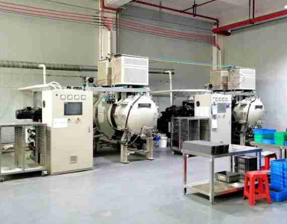
Metal Injection Molding (MIM) has transformed the production of complex metal parts across industries. Sintering is the key step in this innovative manufacturing process. It changes loosely bound metal particles into solid, high-performance parts. This article covers the key principles, steps, and challenges of sintering inMIM technology. It offers useful tips for manufacturers andengineerslooking to increase production.
Sintering in Metal Injection Molding (MIM)is the critical thermal process that facilitates atomic diffusion and neck growth to achieve densification. It transforms the fragile "brown part" into a near-full density, high-strength metal component with superior mechanical properties and final dimensions.
Key Takeaways
- Sintering is the pivotal MIM stage that defines the final density, strength, and accuracy of the metal part.
- Precise control of temperature (up to 1400°C) and atmosphere (Hydrogen/Vacuum) is essential to prevent defects like oxidation.
- Significant linear shrinkage (15-20%) occurs during sintering, requiring accurate tooling design and process control.
- Choosing between Batch and Continuous furnaces depends on production volume, cost constraints, and desired part consistency.
1. Understanding Sintering in Metal Injection Molding
1.1 Definition and Scientific Basis
Sintering is a process that heats metal powder particles and bonds them together without melting. Pressure is also applied during this treatment. Sintering is different from traditional melting. It keeps the metal solid. During this process, atoms move and bond the particles, creating a strong structure with better mechanical properties.
The scientific basis of sintering involves several physical mechanisms:
- Atomic diffusion across particle boundaries
- Reduction of surface energy through particle bonding
- Elimination of internal porosity
- Grain growth and microstructural evolution
These mechanisms work together to transform the fragile "green part" into a strong metal piece, resulting in greater strength, hardness, and stability.
1.2 Role of Sintering in the MIM Process
The completeMIM processconsists of three primary stages:
- Injection molding: Combine metal powder with a binder. Then,inject the mixture into a mold.
- Debinding: Removing the binder from themolded part.
- Sintering: Heating the part to bond the metal particles together.
Sintering is the final and most important stage. Here, the component gets its best mechanical properties and dimensions. This stage determines the quality, performance, and reliability of the finished product.
2. Process Steps of Sintering in MIM
2.1 Pre-Sintering Preparation: Debinding
Before sintering can begin, the binder materials must be completely removed from the molded part. Effective debinding techniques include:
Thermal Debinding:
- Gradually heating the part to decompose and evaporate organic binders.
- Requiring precise temperature control to prevent part deformation.
- Often performed in a specialized furnace with a controlled atmosphere.
Solvent Debinding:
- Immersing parts in organic solvents that dissolve specific binder components.
- Creating a network of pores for subsequent thermal debinding steps.
- Enabling more efficient binder removal while maintaining structural integrity.
Comparative Data: Debinding Methods
| Method | Typical Duration | Binder Removal Rate | Environmental Impact | Cost |
|---|---|---|---|---|
| Thermal | 10-20 hours | 90-95% | Medium | Medium |
| Solvent | 4-12 hours | 60-85% | High | Low |
| Catalytic | 2-6 hours | 95-98% | Low | High |
The debinding process needs careful control. This keeps the part's shape and ensures complete binder removal, preparing the part for successful sintering.
2.2 The Sintering Process
Sintering typically occurs in specialized furnaces under controlled atmospheric conditions. The process involves several critical parameters:
Temperature Control:
- Sintering temperatures for commonMIM materials, like stainless steel, usually range from 1,200 to 1,400°C.
- Temperature must be maintained below the melting point of the metal.
- Temperature ramp rates must be optimized to prevent thermal stress and deformation.
Atmosphere Selection:
- Sintering atmospheres include vacuum, nitrogen, argon, and hydrogen.
- The atmosphere prevents oxidation and other undesirable chemical reactions.
- Different materials require specific atmospheric conditions for optimal results.
Sintering Parameters for Common MIM Materials
| Material | Sintering Temperature (°C) | Optimal Atmosphere | Typical Shrinkage (%) | Density After Sintering (%) |
|---|---|---|---|---|
| 316L Stainless Steel | 1310-1380 | Hydrogen/Vacuum | 14-18 | 96-99 |
| 17-4 PH Stainless | 1280-1350 | Nitrogen/Argon | 15-19 | 95-98 |
| Titanium (Ti-6Al-4V) | 1200-1300 | Vacuum | 16-20 | 95-99 |
| Tungsten Carbide | 1400-1500 | Hydrogen | 20-25 | 97-99.5 |
| Copper Alloys | 950-1050 | Hydrogen | 12-16 | 94-98 |
2.3 Cooling and Post-Processing
After the primary sintering cycle, controlled cooling is essential to:
- Prevent thermal shock and cracking.
- Allow proper microstructural development.
- Minimize residual stresses.
Many MIM components require additional post-processing steps to meet final specifications:
- Surface finishing operations
- Heat treatment for enhanced mechanical properties
- Precision machining for critical dimensions.
- Surface coating or plating for improved performance.
3. Furnace Selection and Impact on Sintering Quality
The choice of sintering furnace significantly impacts the quality of MIM parts. The two primary types of furnaces used in MIM sintering are:
Comparative Analysis: Furnace Types
| Feature | Batch Furnace | Continuous Furnace |
|---|---|---|
| Initial Investment | Moderate | High |
| Production Volume | Low to Medium | High |
| Temperature Uniformity | ±5-10°C | ±3-5°C |
| Cycle Time | 8-24 hours | 4-12 hours |
| Process Flexibility | High | Limited |
| Energy Efficiency | Lower | Higher |
| Floor Space Required | Moderate | Extensive |
| Operating Cost per Part | Higher for large volumes | Lower for large volumes |
Batch furnacesare well suited for:
- Small to medium production runs.
- Research and development
- Companies with diverse product portfolios require frequent material changes.
Continuous furnacesexcel in:
- High-volume production
- Consistent part quality
- Lower per-part operating costs at scale.
4. Common Challenges in MIM Sintering
4.1 Dimensional Control and Shrinkage
One of the most significant challenges in MIM sintering is managing dimensional changes.
- Parts typically shrink by 15-20% during sintering.
- Shrinkage must be predictable and uniform throughout the part.
- Complex geometries may experience differential shrinkage.
Shrinkage Variation Across Materials
| Material | Linear Shrinkage (%) | Volumetric Shrinkage (%) | Shrinkage Variability (±%) |
|---|---|---|---|
| 316L SS | 15-18 | 40-45 | 0.3-0.5 |
| Ti-6Al-4V | 16-20 | 42-49 | 0.4-0.7 |
| Tungsten | 20-25 | 49-58 | 0.5-0.8 |
| Copper | 12-16 | 32-40 | 0.3-0.6 |
Strategies to address shrinkage issues include:
- Precise tooling design, accounting for anticipated shrinkage.
- Careful control of powder characteristics and binder formulation.
- Optimized sintering cycles with controlled heating rates.
4.2 Warping and Sagging
Gravity and internal stresses can cause parts to warp or sag during sintering.
Warping Prevention:
- Design support structures and ribs into the part's geometry.
- Use specialized sintering fixtures and supports.
- Optimize part orientation during sintering.
Sagging Mitigation:
- Custom ceramic trays designed for specific part geometries.
- Sintering in vertical orientations when appropriate.
- Careful control of heating rates to minimize plastic deformation.
Defect Occurrence Rates in MIM Sintering
| Defect Type | Occurrence Rate (%) | Primary Cause | Prevention Method | Detection Method |
|---|---|---|---|---|
| Warping | 8-12 | Uneven shrinkage | Support fixtures | Visual inspection |
| Sagging | 5-10 | Gravity effects | Vertical orientation | Dimensional check |
| Internal porosity | 2-7 | Incomplete debinding | Optimized debinding | X-ray inspection |
| Surface blemishes | 3-6 | Contamination | Clean environment | Visual inspection |
| Cracking | 1-3 | Thermal stress | Gradual heating/cooling | Multiple methods |
4.3 Material-Specific Challenges and Solutions
Different materials present unique sintering challenges:
- Challenge: Chromium oxidation affecting corrosion resistance
- Solution: Hydrogen atmosphere or high-vacuum sintering
Titanium:
- Challenge: High reactivity with oxygen, even at low concentrations.
- Solution: Ultra-high vacuum (10^-5 torr or better) and specialized handling.
Tungsten Carbide:
- Challenge: Very high sintering temperatures lead to furnace limitations
- Solution: Two-stage sintering with controlled cooling between stages
5. Economic Considerations: MIM vs. Alternative Manufacturing Methods
MIM sintering offers economic advantages for specific applications:
Cost Comparison: Manufacturing Methods for Complex Metal Parts
| Manufacturing Method | Tooling Cost | Unit Cost (Low Vol.) | Unit Cost (High Vol.) | Material Utilization (%) | Design Freedom |
|---|---|---|---|---|---|
| MIM | Moderate | Moderate to high | Lower | 97-99 | Very High |
| CNC Machining | Low to moderate | Higher | Moderate | 30-70 | Medium |
| Investment Casting | Moderate | Moderate | Lower to moderate | 90-95 | High |
| Die Casting | Moderate to high | Lower | Lower | 95-98 | Medium |
MIM offers significant advantages for:
- Complex geometries with intricate features
- Medium to high production volumes (1,000–100,000+ parts)
- Applications requiring excellent material properties
- Parts where material wastage is a concern.
6. Practical Applications and Case Studies
6.1 Automotive Industry
MIM sintering enables the production of:
- Fuel injector components with complex internal passages.
- Turbocharger vanes operating at high temperatures
- Locking mechanisms with intricate moving parts
Case Study: A big car maker switched from a conventionally machined fuel injector nozzle to anMIM part. This change reduced production costs and improved flow characteristics, contributing to better fuel efficiency.
6.2 Medical Devices
Themedical industryleverages MIM sintering for:
- Surgical instrumentsrequire complex geometries.
- Orthopedic implants with specific surface textures
- Dental components with precise dimensional requirements.
Case Study: A surgical instrument maker used MIM to create a complex arthroscopic tool with intricate features. The MIM process reduced machining operations and improved product consistency.
6.3 Consumer Electronics
Electronics applicationsinclude:
- Heat sinks with optimized thermal management features
- Connectors require excellent electrical conductivity.
- Structural components with high strength-to-weight ratios.
Case Study: A consumer electronics company used MIM technology to make smartphone camera housings. This change reduced part weight and improved structural rigidity compared with traditional methods.
7. Future Trends in MIM Sintering Technology
The evolving landscape of MIM sintering includes:
Emerging Technologies:
- Low-pressure sintering for enhanced dimensional control
- Microwave-assisted sintering can reduce cycle times substantially.
- Computer modeling for predictive part behavior and reduced development time.
Material Innovations:
- Metal matrix composites with enhanced properties
- Magnetic materials with precisely controlled characteristics.
- Bioabsorbable implantmaterials for medical applications
Conclusion
Sintering is the final step in the MIM process. Here,metal powderparticles turn into fully functional metal parts. Manufacturers can use MIM technology to make complex, high-performance metal parts. By understanding the principles and optimizing process parameters, they can address common challenges. This data-driven method helps them make parts that are tough to create using traditional methods.
Technological advancements are enhancing sintering control and efficiency. Thus, MIM leads in modern metal manufacturing. It provides design freedom, strongmaterial properties, and cost benefits for suitable applications.
Frequently Asked Questions
Q: Q1: How does particle size distribution affect thesintering process?
Particle size distribution significantly impacts sintering behavior. Finer particles, usually 5-20 μm, have a larger surface area for bonding. This leads to faster sintering and higher final densities of 97-99%. But, they cause more shrinkage (16-20%) than coarser powders (12-16% shrinkage). A bimodal distribution of fine and coarse particles often gives the best balance for sintering and size control.
Q: Q2: What are the critical environmental considerations for MIM sintering?
Critical environmental considerations for MIM sintering include energy consumption, gas usage, and the overall carbon footprint compared to traditional machining.
- Energy consumption: 30-60 kWh per kg of sintered material
- Gas usage: 5-15 m³ of protective gas per sintering cycle.
- Carbon footprint: Typically lower than traditional machining when considering material utilization.
- Solvent recovery: Modern systems achieve 85-95% recovery rates for debinding solvents.
Q: Q3: How can sintering defects be detected and measured?
Sintering defects can be detected and measured using X-ray computed tomography, density measurements, metallographic analysis, and coordinate measuring machines.
- X-ray computed tomography: Detecting internal voids as small as 20–50 μm.
- Density measurements: Archimedes method achieving ±0.2% accuracy
- Metallographic analysis: Revealing microstructural features at 500–1000× magnification
- Coordinate measuring machines: Detecting dimensional variations of ±5–10 μm
Precision Metal Parts from Emitech
Nanjing Emitech delivers MIM, CNC machining, and custom metal parts. MIM services · Request a quote
Last updated: 2026-06-24