
Most dimensional variation in MIM parts originates in injection molding—not sintering. Learn the typical tolerance ranges, where variation starts, and design rules to prevent costly failures.
Quick Reference: MIM Tolerance Standards
Standard As-Sintered Tolerances by Feature Size
| Feature Size | Standard Tolerance | Fine Tolerance | Secondary Ops Required For |
|---|---|---|---|
| < 3mm | ±0.06mm | ±0.03mm | < ±0.02mm |
| 3-6mm | ±0.075mm | ±0.05mm | < ±0.03mm |
| 6-15mm | ±0.10mm | ±0.08mm | < ±0.05mm |
| 15-30mm | ±0.15mm | ±0.12mm | < ±0.08mm |
| 30-60mm | ±0.25mm | ±0.20mm | < ±0.15mm |
| > 60mm | ±0.5% | ±0.3% | < ±0.2% |
Critical Design Rules for Dimensional Stability
- Wall thickness:1-6mm (uniform throughout)
- Internal radii:≥0.2mm minimum
- Draft angles:0.5-2° (minimal compared to plastics)
- Thickness transitions:Adjacent sections vary by ≤40-60%
- Gate placement:Thickest cross-section
- Avoid:Sharp corners, non-uniform walls, sections >6mm
GD&T Capabilities (As-Sintered)
- Flatness/Straightness: 0.2% of length (0.1% fine)
- Perpendicularity: 0.3° (0.1° fine)
- Hole location (true position): 0.3% (0.1% fine)
- Surface roughness: Ra 0.8µm typical (0.2µm fine)
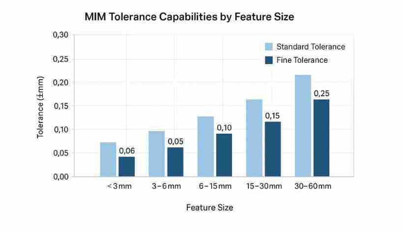
Chart: Tolerance capability comparison across MIM feature sizes
Video: Understanding the Metal Injection Molding Process and Dimensional Control
Where Dimensional Variation Originates: The 4-Stage Tolerance Chain
MIM transforms metal powder into dense components through four sequential stages. Your dimensional accuracy depends on understanding where variation originates and how it amplifies through this chain.
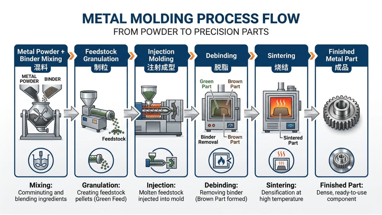
Figure 1: The four-stage MIM process chain and its impact on dimensional tolerances
The Fundamental Challenge: Managing 15-20% Shrinkage
MIM involves massive linear shrinkage during sintering. The ±0.3-0.5% industry standard tolerance represents statistical process variation around this large shrinkage signal. Think of it as managing high-magnitude "signal" (intended 15-20% shrinkage) while minimizing "noise" (process variations causing deviations).
Critical insight:A 1% density variation in the green part manifests as 0.3-0.5% dimensional deviation in the sintered part. This amplification effect explains why early-stage control is paramount.
Stage 1: Feedstock Impact on Tolerances
How it affects dimensions:
- Inconsistent powder particle size distribution → non-uniform packing density → density gradients in green part → differential shrinkage
- Binder viscosity variations → altered flow behavior → molding parameter adjustments required → introduces variability
- Poor feedstock homogeneity → segregation during mold filling → localized density differences → warpage
Control requirement:Feedstock batch-to-batch consistency. Any variation here triggers a multiplicative error chain that amplifies through subsequent stages.
Stage 2: Injection Molding (60-80% of Final Variation Originates Here)
Why this stage dominates dimensional outcomes:
Injection parameters directly control green part density distribution. Non-uniform cavity packing creates density gradients that become differential shrinkage after sintering. Your mold cavity dimensions define the upper limit of achievable accuracy.
Critical parameters affecting tolerances:
| Parameter | Tolerance Impact | Control Requirement |
|---|---|---|
| Injection pressure | Too low: incomplete packing, voids Too high: internal stresses → warpage | ±2-3% shot-to-shot |
| Injection velocity | Affects flow uniformity and packing | ±5% consistency |
| Melt temperature | Alters viscosity, flow patterns | ±2-3°C stability |
| Mold temperature | Controls cooling rate, stress formation | ±3-5°C uniformity |
The multiplicative error chain:
- 0.5% feedstock binder variation
- → Altered viscosity requiring pressure adjustment
- → Changed stress and density distribution
- → Non-uniform green part enters sintering
- → Differential shrinkage rates
- → Final deviation >>0.5%
💡Key Takeaway:If you're experiencing tolerance issues, investigate injection molding consistency first. This stage accounts for 60-80% of final dimensional variation—far more than sintering inconsistencies. Modern high-precision MIM requires closed-loop parameter control with real-time monitoring.
Stage 3: Debinding Impact on Tolerances
How it affects dimensions:
- Non-uniform binder removal → stress gradients → part slumps or distorts before sintering strengthens it
- Rapid binder outgassing → internal pressure → micro-distortions
- Incomplete binder removal → interferes with particle contact during sintering → localized incomplete densification
Control requirement:Uniform, complete binder removal without disturbing the fragile particle network. Any geometric deviation introduced here becomes permanently locked into final dimensions.
Stage 4: Sintering (The Amplification Phase)
How it affects dimensions:
Sintering doesn't create most dimensional problems—it reveals and amplifies issues established during molding. At peak temperature (1,350-1,400°C for stainless steel), pre-existing density gradients cause differential shrinkage rates.
Physical effects on tolerances:
Drag effect:Friction between part and ceramic setter impedes free shrinkage in contact plane. Parts can shrink 0.1-0.2% less in X-Y plane than Z-axis.
Sag effect:At peak temperature, semi-solid parts deform under gravity. Unsupported features with L/D ratios >3:1 are highly susceptible.
Anisotropic shrinkage:Different shrinkage rates along X, Y, Z axes result from:
- Particle orientation during mold filling
- Drag and sag effects
- Flow direction influences from gate location
Control requirements:
- Thermal profile stability (heating rate, peak temperature ±5°C, hold time)
- Atmosphere consistency (prevents oxidation affecting sintering kinetics)
- Part support strategy (stable base surface, appropriate setters)
Practical implication:Centering tolerance on one axis may result in other axes running off-center. Account for this in tolerance allocation and inspection planning.
Design for Dimensional Stability
Your design choices directly determine whether parts will meet tolerance specifications. These principles are countermeasures to specific physical phenomena causing dimensional defects.
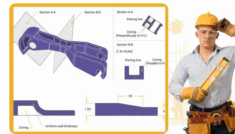
Figure 2: Correct vs. incorrect MIM part design features for optimal dimensional control
Foundation: Uniform Wall Thickness
The single most critical design rule for dimensional stability.
Why it controls tolerances:
- Uniform thickness → uniform flow during molding → consistent packing density
- Uniform thickness → consistent cooling rates → minimal internal stresses
- Uniform thickness → predictable shrinkage during sintering → prevents warpage
Design Guidelines:
| Parameter | Specification | Tolerance Impact |
|---|---|---|
| Ideal range | 1-6mm | Optimal flow and densification |
| Avoid | >6mm sections | Creates porosity, sink marks, unpredictable shrinkage |
| Minimum | 0.3-0.5mm | Below this challenges fill and strength |
| Transitions | ≤40-60% variation | Prevents differential shrinkage |
Coring strategy:When thick features are necessary, core them out. Remove material from centers to create hollow features with uniform walls. This eliminates the primary cause of warpage.
💡Key Takeaway:Non-uniform wall thickness is the #1 design-related cause of tolerance failures. Fix this before optimizing other geometric features. A part with perfect radii and proper draft will still warp if wall thickness varies significantly.
Critical Geometric Features
Radii and Fillets (Stress Management)
Sharp corners concentrate stress causing cracks in green or sintered parts, and impede uniform flow during molding.
- Minimum internal radius:0.2mm
- Preferred range:0.3-0.5mm
- External edges:Round to improve flow
- Tolerance impact:Sharp corners → stress concentrations → cracking → dimensional instability
Ribs and Gussets (Strength Without Mass)
Add strength without violating uniform wall thickness principle.
- Rib thickness:40-75% of attached wall thickness
- Purpose:Structural support with minimal mass
- Tolerance benefit:Prevents need for thick sections that cause differential shrinkage
- Critical:Keep ribs within thickness ratio to prevent opposite-surface sink marks
Holes and Cores
- Prefer through-holes:Two-ended core pin support prevents deflection under injection pressure
- Avoid:Blind holes with L/D >3:1 (cantilevered deflect → inaccurate hole location)
- Tolerance impact:Core pin deflection during molding → hole position deviation
Threads
- External threads:Design narrow flats at parting line (prevents flash, ensures clean form)
- Internal threads:Require unscrewing cores (adds tooling complexity)
- Limitation:Particle size limits edge sharpness to ~0.1mm radius
Tooling Design for Tolerance Control
Gate Placement (Most Critical Tooling Decision)
Cardinal rule:Place gates in the thickest cross-section.
Why this controls tolerances:
- Feedstock flows thick → thin, ensuring uniform cavity packing before thin sections freeze
- Gate in thin section → incomplete thick section packing → density gradients → non-uniform shrinkage
Real example:Medical device pin (Ø2mm × 15mm) with gate in thin section showed ر0.09mm variation. Gate relocation to thick section reduced variation to ±0.06mm (33% improvement).
Parting Line Strategy
- Placement:Non-functional, non-cosmetic surfaces
- Avoid:Placing tight-tolerance features across parting lines
- Reason:Mold misalignment or wear affects cross-parting dimensions
- Tolerance impact:±0.02-0.05mm additional variation on cross-parting features
Ejector Pin Distribution
- Balance:Distribute for uniform ejection force
- Location:Non-critical surfaces
- Purpose:Prevent distortion of warm, soft green part during removal
- Tolerance impact:Unbalanced ejection → part distortion → dimensional deviation
Draft Angles
MIM requires minimal draft (0.5-2°) due to feedstock lubricating properties. This enables truly vertical walls—a significant dimensional advantage over plastic molding.
Sintering Support Design
Stable Base Surface
Design large, flat, stable surfaces serving as reliable bases on ceramic setters. This prevents:
- Tipping/rocking → non-uniform drag effects
- Unstable positioning → variable shrinkage patterns
- Minimum base area:Sufficient to support part weight at semi-solid state (~60% of part footprint)
Supporting Complex Geometries
For parts lacking stable bases or with unsupported features:
Option 1: Temporary support features
- Design removable ribs/feet into MIM part
- Removed post-sintering via breaking or machining
- Provides stability during critical sintering phase
Option 2: Custom ceramic setters
- Shaped fixtures cradling the part
- Support critical features during high-temperature cycle
- Design countermeasure:Use for features with L/D >3:1 to prevent sag
Process Capability Analysis and Control
Statistical Process Control (SPC) for Tolerance Monitoring
SPC detects process instability before significant defective quantities accumulate.
Critical Dimensions to Monitor:
| Monitoring Point | What It Indicates | Control Limit Calculation |
|---|---|---|
| Green part weight | Molding density consistency | X̄ ±3σ from initial study |
| Key sintered dimensions (X,Y,Z) | Anisotropic shrinkage detection | Individual charts for each axis |
| Critical feature dimensions | Process centering and spread | Based on specification limits |
| Surface roughness | Achievable tolerance limits | Ra control chart |
Detecting Anisotropic Shrinkage:
Monitor X, Y, Z dimensions separately. If control charts show process means centered at different percentages of nominal, you have quantified anisotropic shrinkage requiring:
- Gate location adjustment
- Improved part support during sintering
- Targeted machining stock allowances
When to Investigate:
- Points outside control limits:Special cause variation (equipment malfunction, material change)
- Trends:7+ consecutive points moving one direction (tool wear, process drift)
- Patterns:Non-random distributions (systematic issues)
Process Capability Indices (Cpk)
Quantify whether your process can meet specified tolerances.
Formulas:
Cp (Potential Capability):Cp = (USL - LSL) / (6σ)
- Assumes perfect centering
- Measures whether process spread fits within tolerance
Cpk (Actual Capability):Cpk = min[(USL - μ) / (3σ), (μ - LSL) / (3σ)]
- Accounts for process centering
- Measures real-world capability
Interpretation and Action:
| Cpk Value | Process State | Defect Rate | Required Action |
|---|---|---|---|
| < 1.0 | Producing defects | >2,700 PPM | Stop production, investigate root cause |
| 1.0-1.33 | Marginal capability | 63-2,700 PPM | Tighten controls, monitor continuously |
| 1.33-1.67 | Capable process | 0.6-63 PPM | Maintain current controls |
| ≥ 1.67 | Robust process | <0.6 PPM | Excellent performance, continue |
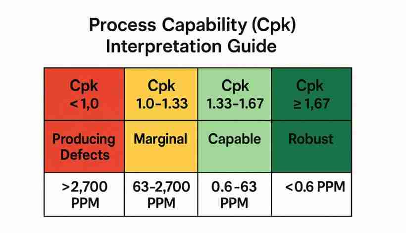
Chart: Process capability (Cpk) interpretation zones and quality levels
Production Release Requirements:
- Minimum:Cpk ≥ 1.33 on all critical dimensions
- Target:Cpk ≥ 1.67 for robust processes
- Never release to production without documented capability studies
Data Collection Requirements:
✅Correct:
- Measure parts in production sequence
- Record ALL parts (passing AND failing)
- Use calibrated gages (resolution ≥1/10th tolerance)
- Minimum 30-50 parts for initial study
❌Incorrect:
- Measuring only good parts (biases results)
- Out-of-sequence measurement (misses trends)
- Inadequate gage resolution (masks true variation)
Predictive Simulation
Mold Flow Analysis Application
Predict and optimize before physical tooling fabrication:
What to simulate:
- Flow pattern uniformity (identifies incomplete fill risk)
- Pressure distribution (reveals packing inconsistencies)
- Weld line locations (predicts weak points)
- Powder-binder segregation risk (indicates potential density gradients)
Optimization decisions enabled:
- Gate location testing (thick vs. thin section placement)
- Runner system sizing (balanced filling)
- Injection parameter prediction (pressure, temperature targets)
Value:Reduce tooling iterations by identifying issues virtually. Each avoided tooling revision saves 6-12 weeks and the cost of a major tool modification.
Sintering Simulation Application
Predict thermal processing outcomes:
- Shrinkage pattern analysis (X, Y, Z axis differences)
- Distortion prediction (identifies high-risk geometries)
- Temperature distribution effects (thick vs. thin section interactions)
Digital Twin Feedback Loop:
- Simulation → Initial process predictions
- SPC → Real-world production monitoring
- CMM → Actual result verification
- Data → Refine simulation models
- Improved predictions → Next project
This cycle continuously enhances prediction accuracy using production data.
Dimensional Inspection Strategy
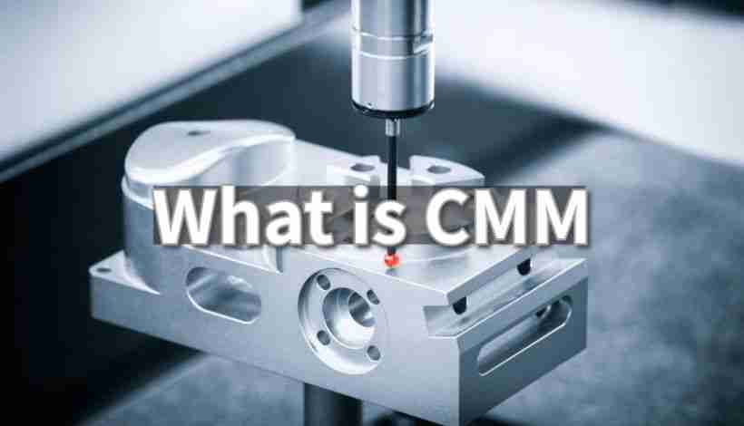
Figure 3: Precision dimensional inspection using coordinate measuring machine (CMM)
Stage-by-Stage Measurement Approach
Measure parts at each process stage to isolate variation sources:
| Process Stage | Key Measurements | What You're Verifying |
|---|---|---|
| Green part | Overall dimensions, weight, critical features | Mold accuracy, molding consistency |
| Brown part | Critical dimensions, geometry | Debinding didn't introduce distortion |
| Sintered part | All specified dimensions, GD&T | Final verification, actual shrinkage |
The diagnostic power:Measuring the same features at all three stages pinpoints exactly where dimensional deviation originates.
Example analysis:
- Green part dimension: 24.00mm (on target)
- Brown part dimension: 23.95mm (slight deviation)
- Sintered part dimension: 19.80mm (off target)
- Conclusion:Debinding stage introduced distortion (brown part deviation); sintering amplified it
Video: Precision measurement techniques for dimensional quality control
Inspection Technology Selection
Coordinate Measuring Machines (CMM):
- Best for:First article inspection, process validation, GD&T verification
- Accuracy:±1-5 microns volumetric
- Application:Detailed dimensional analysis, root cause investigation
Optical Scanning:
- Best for:High-volume production, complex surfaces
- Speed:Millions of points in seconds
- Application:100% inspection, rapid first-article evaluation
Functional Gaging:
- Best for:High-volume go/no-go verification
- Speed:Seconds per part
- Application:Production floor quality checks on critical features
Achieving Precision Beyond Standard Tolerances
When Secondary Operations Are Necessary
Standard MIM achieves ±0.3-0.5% as-sintered. When specific features require tighter tolerances, hybrid manufacturing is often most economical.
Decision framework:
| Your Requirement | Recommended Approach | Expected Result |
|---|---|---|
| Entire part ±0.1% | Optimize MIM process + tight controls | Possible but expensive; high process complexity |
| One feature ±0.02mm | MIM + selective machining on that feature | Most economical; leverages MIM strengths |
| Assembly fit <±0.05mm | MIM + machining/grinding critical surfaces | Common approach; proven economics |
Secondary Operation Options
Coining/Sizing
Cold-forming forcing sintered parts to conform to precision die dimensions.
Best for:
- Improving surface flatness (±0.01-0.02mm)
- Tightening hole diameter tolerances
- Correcting minor dimensional deviations
- Material consideration:Most effective on ductile materials (316L excellent; hard tool steels limited)
Machining Operations
Standard metalworking on sintered parts:
| Operation | Typical Tolerance | Application |
|---|---|---|
| CNC turning/milling | ±0.025mm | Bearing surfaces, critical fits |
| Drilling | ±0.025mm | Precise hole locations |
| Grinding | ±0.012mm | Highest precision surfaces |
| Tapping | Standard thread class | Internal threads |
Design for Hybrid Manufacturing
Machining Stock Allowance:
When planning post-sintering machining, design parts with extra material on finishing surfaces:
- Typical allowance:0.2-0.4mm (0.008-0.016")
- Purpose:Ensures clean cuts removing surface irregularities
- Planning:Identify secondary operation features during design phase—dictates mold design
Economic Example:
Complex bracket with one precision bore:
- All-CNC approach:high material waste and long cycle time
- MIM-only attempt:high scrap rate if bore tolerance is too tight
- Hybrid (MIM + bore grinding):often the most economical approach
💡Key Takeaway:Don't specify tighter-than-necessary tolerances. Use standard MIM tolerances where acceptable; apply secondary operations only where functionally required. Strategic tolerance allocation optimizes cost and manufacturability.
Common Dimensional Defects: Diagnostic Guide
Warpage/Distortion
Symptom:Part twisted, bowed, or bent from intended shape
Root Cause → Solution:
| Root Cause | Diagnostic Check | Solution |
|---|---|---|
| Non-uniform wall thickness | Measure wall thickness variation | Redesign for uniform walls, gradual transitions |
| Uneven cooling during molding | Check mold temperature distribution | Optimize cooling channel design, improve temperature control |
| Internal stress from injection | Measure green part immediately vs. after 24hr rest | Reduce injection pressure, optimize hold time |
| Asymmetric geometry without support | Visual inspection of sintered part orientation | Add sintering support features, use custom setters |
Part-to-Part Dimensional Inconsistency
Symptom:Final dimensions vary significantly between parts or batches
Root Cause → Solution:
| Root Cause | Diagnostic Check | Solution |
|---|---|---|
| Feedstock composition variation | Test powder/binder ratio across batches | Implement tighter feedstock quality controls, batch verification |
| Injection parameter drift | Review SPC control charts on molding machine | Establish closed-loop parameter control, increase monitoring frequency |
| Sintering condition changes | Log furnace thermal profiles, atmosphere data | Enhance furnace calibration, install atmosphere monitoring |
Localized Feature Deviation
Symptom:Specific features consistently out of tolerance while rest of part acceptable
Root Cause → Solution:
| Root Cause | Diagnostic Check | Solution |
|---|---|---|
| Gate in thin section | Review mold design, flow analysis | Relocate gate to thickest section |
| Core pin deflection | Measure hole location variation pattern | Convert blind holes to through-holes, reduce L/D ratio |
| Inadequate sintering support | Identify unsupported features at peak temperature | Add temporary support ribs, use custom setter |
Real-World Application: Dimensional Improvement Example
Component:Surgical instrument pin (Ø2.0mm × 15mm)
Initial Problem:
- Specification:Ø2.00mm ±0.04mm
- Actual capability:±0.09mm
- Cpk:below acceptable level
- Scrap rate:high
Root Cause Analysis:
Step 1: Stage-by-stage measurement
- Green part showed high diameter variation
- Identified molding as primary variation source
Step 2: SPC data review
- Shot-to-shot weight variation excessive
- Correlated with diameter deviation
Step 3: Mold design review
- Gate located in thin section (Ø2mm end)
- Causing non-uniform packing density
Solutions Implemented:
- Gate relocated to thicker section
- Tighter closed-loop pressure/temperature control
- Added machining stock allowance on diameter
- Post-sintering centerless grinding for final precision
Results:
- As-sintered diameter:improved substantially
- Post-grinding diameter:within specification
- Cpk:reached robust levels
- Scrap rate:<2%
Key Lessons:
- Root cause was gate placement (design issue), not process capability
- Hybrid approach (MIM + selective grinding) often provides better economics than attempting ultra-tight as-sintered tolerances
- Stage-by-stage measurement isolates variation sources quickly
Frequently Asked Questions
Q: What is the tightest tolerance achievable with MIM?
As-sintered MIM typically achieves ±0.3-0.5% of nominal dimensions. Optimized processes with tight controls can reach ±0.05-0.2% (fine tolerances). For precision beyond these capabilities, secondary operations like machining or grinding achieve tolerances as tight as ±0.012mm (0.0005") on specific features. The economic sweet spot is often hybrid manufacturing: standard MIM tolerances where acceptable, selective secondary operations only on critical features.
Q: Why do my parts show different shrinkage in X, Y, and Z directions?
Anisotropic shrinkage occurs due to: (1) Particle and polymer chain orientation during mold filling creates directional material properties; (2) "Drag effect" from friction between part and setter impedes shrinkage in contact plane; (3) "Sag effect" causes gravitational deformation in unsupported features at peak temperature. Quantify using SPC by monitoring X, Y, Z dimensions separately. Solutions: optimize gate location for balanced filling, improve sintering support, or add targeted machining stock allowances on off-center axes.
Q: How much machining stock should I leave for post-sintering operations?
For surfaces requiring post-sintering machining, design 0.2-0.4mm (0.008-0.016") of stock. This ensures sufficient material for clean cuts while minimizing machining time. Identify features requiring secondary operations during the design phase—this dictates both mold design and manufacturing planning. Don't add stock to features that don't need it; this wastes material and increases costs.
Q: What's the most important factor for controlling MIM tolerances?
Injection molding consistency is paramount—60-80% of final dimensional variation originates here. Priority controls: (1) Stable injection pressure/velocity (±2-3% shot-to-shot); (2) Temperature control (±2-3°C melt, ±3-5°C mold); (3) Proper gate placement (thickest cross-section); (4) Monitor green part weight as a real-time density indicator. However, true precision requires holistic control: feedstock consistency, injection parameters, debinding uniformity, and sintering cycle stability must all be managed systematically.
Q: How do I verify my MIM process is capable before production release?
Calculate the process capability index (Cpk) using production measurement data. Requirements: (1) Cpk ≥ 1.33 minimum for production release; (2) Cpk ≥ 1.67 for robust processes. Data collection protocol: Measure parts in production sequence, use calibrated gages (resolution ≥1/10th tolerance), collect minimum 30-50 parts, and verify process stability via SPC control charts before calculating capability. Never release to production without documented capability studies on critical dimensions.
Q: Should I specify tighter tolerances than functionally necessary?
No. Specify tight tolerances only on functionally critical features. Unnecessarily tight specifications: (1) Increase tooling costs; (2) Reduce process yields; (3) May require expensive secondary operations; (4) Extend lead times. Best practice: Work with your MIM supplier during the design phase to identify which features truly require precision beyond standard ±0.3-0.5% capabilities. Strategic tolerance allocation—tight where necessary, relaxed elsewhere—optimizes both cost and manufacturability.
Q: When should I add secondary machining instead of tightening the MIM process?
Add secondary machining when: (1) Required tolerance is significantly tighter than the ±0.3-0.5% standard capability; (2) Only specific features need tight tolerance (not the entire part); (3) Production volume justifies secondary operation tooling/setup; (4) Feature is critical for assembly or function. Economic comparison: Attempting ultra-tight as-sintered tolerances across entire parts often costs more than hybrid MIM + selective machining due to high scrap rates and expensive process controls required.
Q: What causes parts to warp during sintering and how do I prevent it?
Warpage results from differential shrinkage rates within the part. Primary causes and solutions: 1) Non-uniform wall thickness: Thick sections shrink differently than thin sections, so redesign for uniform walls (1-6mm) and gradual transitions (≤40-60% variation). 2) Density gradients from molding: Non-uniform cavity packing means you must optimize gate location (thickest section) and tighten injection parameter controls. 3) Inadequate sintering support: Unsupported features sag at peak temperature, so add a stable base surface, temporary support ribs, or custom setters. Prevention hierarchy: (1) Design for uniform walls first; (2) Optimize molding consistency second; (3) Add sintering supports third.
Conclusion: The Path to Dimensional Precision in MIM
Dimensional control in Metal Injection Molding requires understanding that you're managing a massive, intentional transformation—not eliminating change, but ensuring consistency in 15-20% linear shrinkage. The ±0.3-0.5% industry standard tolerance represents statistical process variation around this large shrinkage signal.
The Critical Success Framework:
1. Recognize the Variation Source Hierarchy
- 60-80% originates in injection molding (not sintering)
- Early-stage inconsistencies amplify through subsequent stages
- This multiplicative error chain demands upstream control
2. Design as Your First Line of Defense
- Uniform wall thickness (1-6mm) prevents most warpage
- Appropriate radii (≥0.2mm) eliminate stress concentrations
- Proper gate placement (thickest section) ensures uniform packing
- Stable sintering support prevents sag and drag effects
3. Implement Systematic Process Control
- Closed-loop injection parameter control (pressure ±2-3%, temperature ±2-3°C)
- SPC monitoring of critical dimensions (green weight, sintered X/Y/Z)
- Process capability verification (Cpk ≥1.33 minimum before release)
- Stage-by-stage measurement for rapid problem isolation
4. Apply Strategic Tolerance Allocation
- Specify tight tolerances only where functionally required
- Use standard MIM capabilities (±0.3-0.5%) where acceptable
- Apply secondary operations selectively on critical features
- Hybrid manufacturing often provides optimal economics
5. Leverage Predictive Tools
- Mold flow simulation before tooling fabrication
- SPC during production for real-time problem detection
- Precision inspection for verification and continuous improvement
- Digital twin feedback loop enhancing prediction accuracy
From Reactive to Proactive:
Move from "inspect and reject" to "predict and prevent" by:
- Simulating before building physical tooling
- Monitoring process stability in real-time
- Verifying capability before production release
- Feeding production data back to refine predictions
Final Perspective:
MIM offers unique capabilities for producing geometrically complex metal components economically at high volumes. Dimensional precision is achievable, but requires recognizing that dimensional variation is the cumulative result of a tolerance chain where early decisions cascade through the entire process.
Master the fundamentals: understand where variation originates (60-80% from molding), design to prevent problems (uniform walls, proper gating), monitor systematically (SPC and Cpk), and apply secondary operations strategically (only where functionally required).
By implementing these principles, you can consistently achieve the dimensional precision your applications demand while maximizing the economic advantages MIM provides for complex, high-volume metal component production.
Precision Metal Parts from Emitech
Nanjing Emitech delivers MIM, CNC machining, and custom metal parts. MIM services · Request a quote
Last updated: 2026-06-24
Continue reading
- Rack and Pinion Systems: Engineering Specification Guide
- Safety-Critical MIM Applications in Automotive: Airbag Systems, Seatbelt Mechanisms & Braking Components
- Essential Guide to Sintered ABS Rings: What You Really Need to Know
- The Ultimate Guide to Sintered Bearings: Self-Lubricating Solutions for Modern Engineering