
Powder Metallurgy Surface Finish
Your PM part just failed inspection at Ra 6.0 µm—but you designed it for Ra 1.6 µm. The problem? You didn't specify the measurement method. In powder metallurgy, surface finish isn't just a number—it's a dual-characteristic topography where your choice of stylus can make or break your quality control.
Emitech delivers custom MIM parts with as-sintered Ra 0.8–1.6 μm plus polishing, plating, and coating options — request a quote.
Quick Reference: Typical PM Surface Finish Values
| PM Process | Typical As-Sintered Ra (µm) | Typical As-Sintered Ra (µin) |
|---|---|---|
| Conventional Press-and-Sinter | 1.6-3.2 µm | 63-125 µin |
| Metal Injection Molding (MIM) | 0.2-1.2 µm | 8-47 µin |
| Metal Additive (DMLS/SLM) | 5-20 µm | 200-790 µin |
CRITICAL: Always specify measurement method in your technical drawings (ASTM B946 Method 1 or Method 2)
Understanding the Unique Nature of PM Surface Finish
When you ask "what is the surface finish of powder metallurgy," you're asking a more complex question than you might realize. Unlike machined or cast parts, PM components have a fundamentally different surface structure that defies simple characterization.
The Dual-Characteristic Surface: More Than Just Roughness
Your PM part's surface isn't a single, continuous plane. It's accurately described as "a series of very smooth surfaces which are interrupted with pores of varying sizes." This dual nature creates both opportunities and challenges:
The Texture Component: The consolidated metal particles themselves, which can be remarkably smooth depending on your powder size and sintering parameters.
The Porosity Component: The open, interconnected voids that extend to the surface—not defects, but intrinsic features of the powder metallurgy process.
This porosity serves contradictory roles in your application:
As a liability: Surface pores act as stress concentrators and crack initiation sites, directly limiting your part's fatigue life. They create pathways for corrosion and cause "bleed-out" of trapped fluids after plating operations.
As an asset: These same pores function as lubricant reservoirs in bearings and gears, providing self-lubrication that wrought components simply cannot match. In PM filters, controlled porosity is the entire functional purpose.
What This Means for Your Design
Understanding this dual nature is critical because it affects every downstream decision you make:
- How you measure surface finish (stylus selection)
- Which roughness parameter you specify (Ra vs Rz)
- What secondary operations are required (sealing vs leveraging porosity)
- How your part will perform in service (fatigue life, wear resistance, sealing capability)
The surface finish of powder metallurgy is not a defect to be minimized—it's an engineered characteristic to be controlled and, in many cases, exploited for functional advantage.
The Critical Measurement Problem You Need to Solve
Here's where most engineers make their first mistake: specifying "Ra 1.6 µm max" on a drawing without understanding the measurement method.
ASTM B946: Two Methods, Completely Different Results
The governing standard, ASTM B946 ("Standard Test Methods for Surface Roughness of Powder Metallurgy Products"), explicitly defines two incompatible measurement procedures:
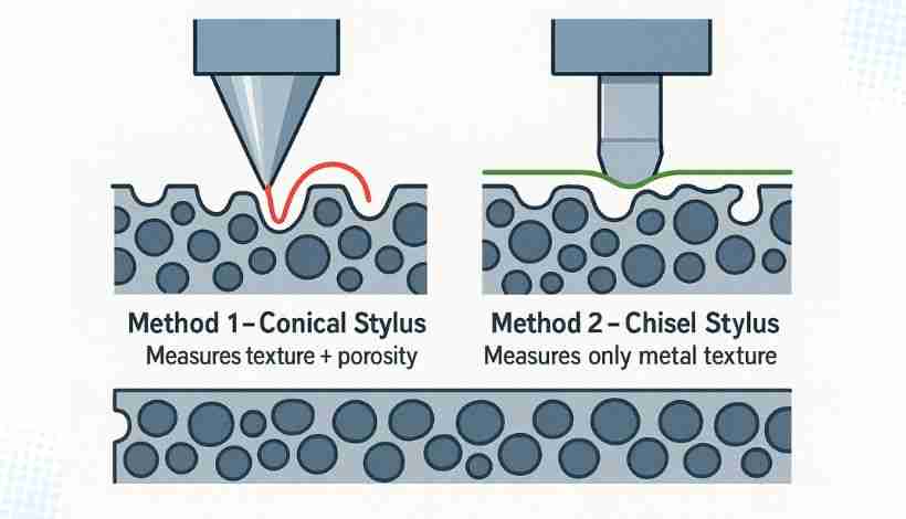
Method 1 - Conical Stylus with Gaussian Filter
This uses your standard profilometer stylus (typically 2-10 µm tip radius). When it traverses your PM surface, the conical stylus drops into surface pores, measuring their depth rather than the actual metal texture. Result: artificially inflated roughness values that include porosity interference.
Method 2 - Chisel (Knife-Edge) Stylus
This uses a wide, flat-edged stylus specifically designed to bridge over surface pores, measuring only the actual consolidated metal surface—the true bearing surface your part will use in operation.
The Quality Control Nightmare
A functionally perfect component can have two entirely valid but wildly different Ra values:
- Method 2 (chisel stylus): Ra 1.6 µm → PASS
- Method 1 (conical stylus): Ra 6.0 µm → FAIL
The same part, the same surface, different results. Without specifying the measurement method in your technical drawing, your specification is unenforceable. The agreement between you and your supplier on measurement methodology is more important than the numerical value itself.
Why This Problem Exists
The ASTM B946 standard explicitly states that conventional PM materials "contain open porosity at the surface... the porosity... will negatively influence this value." This isn't a measurement error—it's a fundamental metrology challenge created by the dual-characteristic nature of PM surfaces.
When a conical stylus encounters a surface pore, it doesn't measure the smoothness of the metal—it measures the depth of the void. The instrument cannot distinguish between a rough metal surface and a smooth metal surface interrupted by pores. This is why the chisel stylus was developed: to intentionally ignore the porosity component and measure only the texture component.
Practical Implications for Your Specifications
If you want to measure the actual metal texture (the bearing surface that contacts mating parts), you must specify ASTM B946 Method 2 with chisel stylus. If you want to measure the combined effect of texture plus porosity (relevant for sealing applications or coating adhesion), specify Method 1 with conical stylus.
The worst scenario is specifying neither—leaving the measurement method up to interpretation. This guarantees inconsistent results and supplier disputes.
Video demonstration of surface roughness measurement on powder metallurgy components using profilometer equipment per ASTM B946 standard
Ra vs. Rz: Why You're Probably Measuring the Wrong Parameter
If you're designing fatigue-critical PM components and only specifying Ra, you're using the wrong metric.
The Ra Problem: Averaging Hides Your Biggest Threats
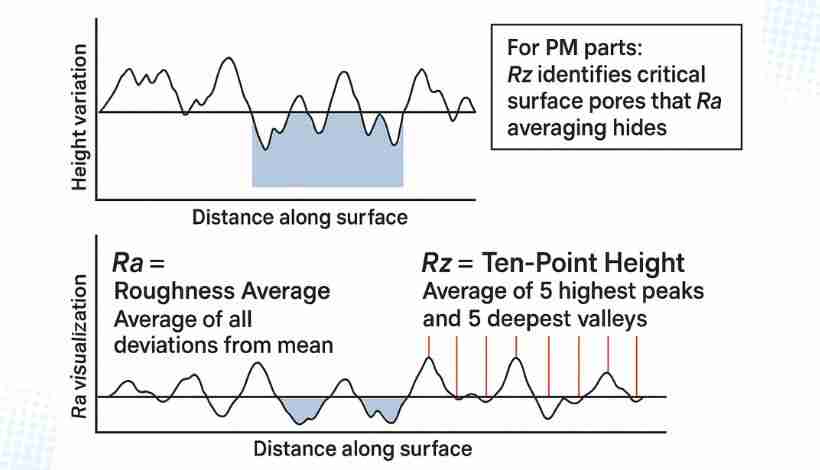
Ra (Roughness Average) is the arithmetic mean of surface deviations. While it's the most common parameter in manufacturing, it has a fatal flaw for PM parts: it averages out the outliers.
Your PM part's fatigue life isn't determined by average roughness—it's governed by "the size of the greatest pores situated at the surface." These deep valleys act as stress concentrators and crack nucleation sites. Ra, by its statistical nature, hides these critical defects.
The Rz Solution: Designed to Find Your Worst Pores
Rz per ISO 4287 measures the average of five highest peaks and five deepest valleys; per ISO 21920, Rz is the maximum peak-to-valley height within the evaluation length. Either way, Rz captures worst-case surface features that Ra averages out. For PM components, this is your functionally relevant metric.
Real-World Example: The Shot Peening Paradox
A Metal Injection Molding component case study illustrates this perfectly:
Before shot peening:
- Ra: 1.24 µm (suggests smooth surface)
- Rz: 36.24 µm (reveals deep pores)
After shot peening:
- Ra: 2.56 µm (increased - appears worse)
- Rz: 16.59 µm (decreased 54% - actually better)
Shot peening replaces a dangerous topography (sharp, deep, fatigue-initiating pores) with a beneficial one (shallow, rounded, compressive-stress dimples). The process closes surface porosity and dramatically improves fatigue life, even though the Ra number gets worse.
This is the clearest illustration of why Ra alone is insufficient for PM performance evaluation. The average got rougher, but the worst-case features—the ones that actually cause failure—improved dramatically.
When to Use Each Parameter
Specify Ra when:
- You need a general smoothness specification
- You're comparing similar manufacturing processes
- Surface appearance or feel is important
- You're working with non-critical structural parts
Specify Rz when:
- Fatigue life is critical (connecting rods, gears, springs)
- You need to control worst-case surface features
- Coating adhesion depends on peak-to-valley depth
- Sealing performance is sensitive to deep surface defects
For critical PM components, specify both: Ra for general quality and Rz as a functional limit.
What Surface Finish Can You Actually Achieve?
Your achievable surface finish is determined by three factors: your PM process, your powder characteristics, and your processing parameters. Here's what you can realistically expect in the as-sintered condition.
Conventional Press-and-Sinter (P&S)
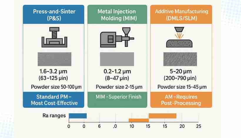
Typical As-Sintered Values: Ra 1.6-3.2 µm (63-125 µin)
This is your most cost-effective PM process, delivering surface finish equivalent to standard CNC machining—but without the machining cost. The variation in this range depends on:
Powder particle size: Coarser particles (50-100 µm) produce rougher surfaces. This is not a cost-cutting measure—it's a processing necessity. Fine powders have poor flowability and won't fill your die cavity uniformly in conventional press-and-sinter.
Part density: Higher compaction pressure creates smaller, more isolated pores. A low-density part (6.0 g/cm³) will have larger, more interconnected surface pores than a high-density part (7.2 g/cm³).
Surface orientation: Sidewall features often achieve better than Ra 1.6 µm due to "ejection burnishing." The high-pressure sliding action as your part exits the die plastically smooths the vertical surfaces. This creates anisotropic surface finish—sidewalls are smoother than top and bottom faces.
The P&S Limitation: Conventional press-and-sinter fundamentally requires coarse powders because finer powders won't flow. This powder size constraint places a physical limit on the best-achievable as-sintered finish. You cannot simply "use finer powder" in P&S—the process won't work.
Metal Injection Molding (MIM)
Typical As-Sintered Values: Ra 0.8–1.6 µm (32–63 µin)
Standard Value: Ra 0.8 µm (32 µin)
MIM delivers 2-4x better surface finish than conventional P&S. This isn't marketing—it's the direct result of using ultra-fine metal powders.
The MIM Advantage: MIM uses ultra-fine metal powders (2-15 µm particles) mixed with a polymer binder system. The binder flows under heat and pressure like a thermoplastic, carrying the fine, non-flowable powders into every detail of your mold cavity. After debinding and sintering, you're left with a fine, homogeneous surface texture often described as "matt" or "pear-skin" finish.
Why MIM Exists: MIM was developed specifically to overcome the flowability limitation of press-and-sinter. The binder system is the technological unlock that enables ultra-fine powders, thereby achieving as-sintered finishes impossible with conventional PM.
Achievable Range:
- Standard MIM: Ra 0.8 µm (competitive with fine CNC machining)
- Optimized MIM: Ra 0.3-0.5 µm (with premium mold quality and powder selection)
- Best-case mass production: Ra 0.2 µm (approaching grinding quality)
When to Choose MIM: Small, highly complex, high-volume parts where exceptional as-sintered finish is critical. Medical devices, precision electronics, and consumer-facing components are ideal applications. The higher material and processing costs are justified by the elimination of secondary finishing operations.
Metal Additive Manufacturing (DMLS/SLM)
Typical As-Built Values: Ra 5-20 µm (200-790 µin)
After Standard Bead Blasting: Ra 5-12 µm
Powder bed fusion processes are notorious for poor surface finish—it's consistently cited as a key limitation of the technology.
Why AM Surfaces Are Rough:
Your surface roughness in additive manufacturing comes from multiple sources:
- Stair-stepping: Layer-by-layer approximation of curved surfaces creates visible steps
- Partially melted particles: Loose powder from the bed adheres to the part during the build
- Melt pool dynamics: Remelting of the previous layer creates texture
- Process parameters: Laser power, scan speed, and layer thickness all significantly impact final Ra
The Anisotropy Problem: A single AM component has no single Ra value—roughness varies dramatically based on build orientation:
- Top surfaces (facing up, directly laser-processed): Smoothest (Ra 5-8 µm)
- Vertical sidewalls: Rougher (Ra 8-15 µm)
- Downskin surfaces (facing powder bed): Roughest (Ra 15-25 µm)
Critical Takeaway: If you're choosing metal additive manufacturing, assume all functional, mating, or tolerance-critical surfaces will require mandatory CNC machining to achieve acceptable finish. AM is a "near-net-shape" process that always needs post-processing for critical surfaces.
When AM Makes Sense: Choose AM only when geometric complexity is your primary driver—internal cooling channels, topology-optimized structures, or consolidation of multi-part assemblies. The rough surface finish and high processing costs must be justified by the design advantages.
Primary Process Parameters: Engineering Your Surface from the Start
Your as-sintered surface finish isn't an accident—it's the predictable outcome of your powder selection, compaction parameters, and sintering cycle. Understanding these relationships allows you to engineer surface finish from the beginning of the design process.
Complete powder metallurgy manufacturing process showing compaction and sintering stages that determine final surface finish characteristics
Powder Characteristics: Your Genetic Material
Particle Size: The single most dominant factor in your final surface texture.
The relationship is direct and quantifiable:
- Finer powders → smoother surfaces (but processing challenges)
- Coarser powders → rougher surfaces (but better flowability)
Studies show that processing coarser particles results in 20-50% higher Ra values compared to fine powders. In Metal Injection Molding, using ultra-fine metal powder with an average particle diameter of 2 µm has achieved as-sintered surface finish as low as Ra 0.2 µm in mass-produced products.
However, you cannot simply choose the finest possible powder. Very fine powders (5-15 µm particle size distribution) exhibit poor flowability. They have high surface-area-to-volume ratio and strong interparticle friction, causing them to agglomerate or "clump" together. This clumping behavior prevents the powder from flowing under gravity to uniformly fill die cavities in conventional press-and-sinter.
This flowability trade-off explains the fundamental difference between P&S and MIM:
- P&S limitation: Must use coarse powders (50-100 µm) for flowability → limits best-achievable finish to Ra 1.6-3.2 µm
- MIM solution: Binder system acts as carrier for fine powders (2-15 µm) → enables finish of Ra 0.2-0.8 µm
Other Critical Powder Characteristics:
Particle shape: Spherical powders pack more uniformly than irregular particles, producing smoother surfaces and more consistent density. Water-atomized powders (irregular shape) produce rougher surfaces than gas-atomized powders (spherical).
Oxidation: Oxidized powders lead to clumping and the formation of fine pores during sintering, which degrades surface integrity and mechanical properties. Surface oxide films interfere with particle bonding during sintering.
Powder recycling: In additive manufacturing, recycled powders (a common cost-saving measure) exhibit shape degradation. Spherical particles become more irregular after repeated thermal cycling. This translates into increased surface roughness and porosity in the final part.
Compaction Pressure: Controlling Porosity, Not Texture
Higher compaction pressure doesn't significantly change your micro-scale texture (which is set by powder particle size), but it fundamentally alters your macro-scale porosity.
The Pressure-Porosity Relationship:
As compaction pressure increases, the surface contact area between powder particles increases. This reduces both the number and volume of pores, leading to higher green density. The effect is:
- Higher pressure(500-800 MPa): Smaller pores, isolated and rounded, higher density (7.0-7.4 g/cm³)
- Lower pressure(300-500 MPa): Larger pores, irregular and interconnected, lower density (6.0-6.8 g/cm³)
Why This Matters for Performance:
For high-performance applications, this relationship is critical. Your part's fatigue life is governed by the size of your largest surface pores—these act as crack nucleation sites. Compaction pressure is your primary tool for improving fatigue life, not by changing Ra, but by minimizing the size of surface pores.
A high-density part (7.2 g/cm³) has superior functional surface finish compared to a low-density part (6.4 g/cm³), even if their particle-level Ra values are identical. The high-density part has smaller, more rounded pores that are less likely to initiate fatigue cracks.
Engineering Specification: For fatigue-critical components (connecting rods, gears, high-stress structural parts), specify minimum sintered density in addition to surface finish. A typical requirement might be "minimum 7.0 g/cm³ density with Ra 2.0 µm max per ASTM B946 Method 2."
Sintering: Thermal Pore Rounding
Sintering is the high-temperature thermal process that fuses compacted particles into a solid, coherent mass through atomic diffusion, without melting the bulk material. Your sintering parameters—specifically temperature, time, and atmosphere—have direct impact on pore morphology.
The Pore Rounding Effect:
While high-temperature sintering increases overall part density through continued particle bonding, its most important effect on the surface is pore rounding. During the sintering cycle, atomic diffusion acts to minimize surface energy. This process transforms angular, sharp-cornered voids (high stress concentration points) into smoother, more spherical pores.
This thermal "smoothing" of pore morphology reduces internal stress concentrators, thereby improving the material's ductility and fatigue strength. A sharp-cornered pore with stress concentration factor of 3-5x can be rounded to 1.5-2x through proper sintering.
Your Two Process Levers:
The manufacturing process provides two distinct controls for surface characteristics:
- Compaction pressuredetermines the volume and quantity of porosity
- Sintering cycledetermines the morphology and shape of that porosity
Both are critical for producing a high-performance functional surface. High pressure alone won't give you good fatigue performance if your pores remain sharp and angular. Optimal sintering temperature and time are required to round those pores into less-dangerous features.
Typical Sintering Parameters:
- Temperature: 1120-1150°C for iron-based PM
- Time: 20-40 minutes at temperature
- Atmosphere: Protective (nitrogen-hydrogen blend or dissociated ammonia)
Higher sintering temperatures and longer times promote more complete pore rounding, but must be balanced against dimensional control, grain growth, and economic considerations.
Comparative Benchmarking: How PM Stacks Up Against Other Processes
Understanding where PM surface finish sits relative to competing manufacturing processes helps you make informed design decisions and communicate realistic expectations to stakeholders.
PM vs. Casting Processes
| Casting Process | Typical Ra (µm) | Typical Ra (µin) | PM Comparison |
|---|---|---|---|
| Sand Casting | 6.4-25 | 250-1000 | All PM processes significantly superior |
| Investment Casting | 1.6-6.3 | 63-250 | P&S competitive; MIM significantly better |
| Die Casting | 0.8-8.0 | 32-320 | MIM comparable to best die casting |
Detailed Analysis:
vs. Sand Casting: Sand casting uses a sand mold, which produces a very rough surface reflecting the sand grain texture. Typical values are Ra 12.5-25 µm, with Ra 6.4 µm considered "good" for sand casting. Even the roughest PM process (metal AM at Ra 5-20 µm) is competitive with or better than sand casting.
vs. Investment Casting: This process uses a ceramic mold to produce "good" finish. Typical Ra ranges from 1.6-6.3 µm, with Ra 3.2 µm being a common average. High-end investment casting can achieve Ra 0.8 µm.
Verdict: Conventional P&S PM (at Ra 1.6-3.2 µm) is directly competitive with or superior to typical investment casting. Metal Injection Molding (at Ra < 0.8 µm) significantly outperforms all but the most precise investment castings.
vs. Die Casting: Die casting injects molten metal into hardened steel molds, producing the best finish of all casting methods. Reported values range from Ra 0.8-1.6 µm for high-quality operations to Ra 4-8 µm for typical production. Best-case die casting can achieve Ra 0.5 µm.
Verdict: High-quality die casting (Ra ~1.0 µm) is superior to as-sintered P&S PM (Ra 1.6-3.2 µm). However, high-quality MIM (Ra 0.2-0.8 µm) is comparable to or significantly better than typical die casting.
PM vs. CNC Machining: The Economic Value Proposition
This is the most critical comparison for understanding the economic value of powder metallurgy.
| Machining Process | Typical Ra (µm) | Typical Ra (µin) | Cost Level |
|---|---|---|---|
| Standard CNC Machining | 3.2 | 125 | Moderate |
| Fine CNC Machining | 1.6 | 63 | Higher |
| Smooth CNC Machining | 0.8 | 32 | Higher |
| Grinding | 0.1-0.4 | 4-16 | Very High |
| Lapping | 0.025-0.1 | 1-4 | Extremely High |
The Core Value Proposition:
Conventional P&S PM(Ra 1.6-3.2 µm) delivers standard CNC-machined finish without machining costs. This is the economic driver of powder metallurgy: it eliminates the need for most, if not all, secondary machining operations for structural parts. A P&S gear or bearing can be used as-sintered in many applications, saving significant manufacturing cost compared to machining from bar stock.
Metal Injection Molding(Ra < 0.8 µm) delivers fine CNC finish quality on highly complex geometries that would otherwise require extensive multi-axis machining or grinding. MIM can produce features impossible or impractical to machine (undercuts, internal features, thin walls) while maintaining excellent surface finish.
Metal Additive Manufacturing(Ra 5-20 µm) delivers rough finish comparable to rough sand casting—not acceptable for most functional applications. AM is a "near-net-shape" process that always requires post-machining of critical surfaces. The economic value of AM comes from geometric complexity and part consolidation, not from surface finish.
The Functional Advantage: Beyond the Numbers
An Ra 1.6 µm PM surface is not functionally identical to an Ra 1.6 µm machined surface, even though the numbers match:
Machined surface characteristics:
- Directional tool marks (lay) oriented in cutting direction
- Solid, non-porous substrate
- Requires external lubrication in tribological applications
Sintered PM surface characteristics:
- Generally isotropic (non-directional) texture
- Controlled porosity for lubricant retention
- Self-lubricating capability in bearings and gears
In tribological applications (sliding wear, rolling contact), the PM surface's ability to retain lubricants in surface pores can provide significant functional advantage over a "smoother" solid component. This is why PM bearings and gears often outperform machined equivalents in wear resistance and friction performance, despite having similar or slightly higher Ra values.
How to Properly Specify PM Surface Finish
Proper specification of PM surface finish requires understanding the unique measurement challenges and functional requirements of powder metallurgy components. A simple Ra callout is insufficient and often leads to quality disputes.
Rule 1: Specify Method, Not Just Number
The most critical specification requirement is identifying the measurement method.
❌Wrong: "Ra 1.6 µm max"
✅Right: "Ra 1.6 µm max per ASTM B946, Method 2 (chisel stylus)"
Why this matters: Without method specification, your supplier might use a conical stylus (Method 1) that drops into pores and measures Ra 6.0 µm on a functionally perfect part. Your drawing specification must explicitly state:
- Standard: ASTM B946 or MPIF Standard 58
- Method: 1 (conical stylus) or 2 (chisel stylus)
- For most applications: Method 2 is appropriate, as it measures the actual bearing surface
Additional specification details:
- Cutoff length (typically 0.8 mm or 2.5 mm)
- Evaluation length (typically 5x cutoff length)
- Measurement direction (if anisotropy is expected)
- Number of measurements required for acceptance
Rule 2: Specify Rz for Critical Applications
For any dynamically loaded or fatigue-critical part (connecting rods, gears, hydraulic components, springs), Ra alone is insufficient.
Recommended specification format:
- "Ra 2.0 µm max, Rz 12.0 µm max per ASTM B946 Method 2"
This dual specification provides:
- Ra control: General surface quality
- Rz control: Direct limit on worst-case surface features (deepest pores)
The Rz limit is your engineering control against fatigue-initiating surface defects. A part can pass Ra 2.0 µm with deep isolated pores that give Rz 25 µm—this part will fail prematurely in fatigue. The Rz specification prevents this scenario.
Rule 3: Understand and Account for Anisotropy
Your finish is not uniform across all surfaces of the part.
Press-and-Sinter anisotropy:
- Sidewalls (perpendicular to pressing direction): Smoother due to ejection burnishing
- Top/bottom faces (parallel to pressing direction): Rougher, reflects punch finish
Metal AM anisotropy:
- Top surfaces (facing up): Smoothest
- Vertical sidewalls: Rougher
- Downskin surfaces (facing powder bed): Roughest
Practical approach: Apply surface finish specifications only to functionally critical surfaces (bearing surfaces, sealing surfaces, mating surfaces) rather than global part specification. Use datum references and surface symbols to identify which surfaces require control.
Example specification:
- Critical bearing surface: "Ra 1.6 µm max per ASTM B946 Method 2"
- Non-critical surfaces: "As-sintered finish acceptable"
Rule 4: Consider Density Specification for Fatigue Applications
For fatigue-critical components, surface finish specification alone is insufficient. Specify minimum sintered density to control subsurface porosity and surface pore size.
Recommended format:
- "Minimum sintered density 7.0 g/cm³, Ra 2.0 µm max, Rz 12.0 µm max per ASTM B946 Method 2"
Higher density correlates with smaller surface pores, which directly improves fatigue performance. This specification prevents scenarios where a part meets surface finish requirements but has inadequate density for the loading conditions.
Frequently Asked Questions About PM Surface Finish
Q: What is the typical surface finish of a powder metallurgy part?
The typical surface finish depends on your PM process:
- Conventional press-and-sinter: Ra 1.6-3.2 µm (63-125 µin)
- Metal injection molding (MIM): Ra 0.8–1.6 µm (32–63 µin)
- Metal additive manufacturing (DMLS/SLM): Ra 5-20 µm (200-790 µin) as-built
These values are for as-sintered condition before any secondary finishing operations. Surface finish varies within each process based on powder size, part density, and sintering parameters.
Q: Why do I get different roughness readings on the same PM part?
You're likely using different measurement methods. ASTM B946 defines two incompatible procedures:
- Method 1 (conical stylus): Measures combined surface texture plus porosity—stylus drops into pores, giving higher Ra values
- Method 2 (chisel stylus): Measures only consolidated metal surface—stylus bridges over pores, giving lower Ra values
The same part can measure Ra 1.6 µm with chisel stylus but Ra 6.0 µm with conical stylus. Always specify your measurement method explicitly in technical drawings to prevent quality disputes.
Q: Is Ra or Rz more important for powder metallurgy components?
Rz is more functionally relevant for PM parts, especially in fatigue-critical applications. Here's why:
- Rais an average that hides deep surface pores
- Rzspecifically measures the five deepest valleys—directly quantifying your largest, most dangerous surface pores
- Your PM part's fatigue life is governed by the size of the greatest surface pores, not average roughness
For critical components, specify both: Ra for general surface quality control and Rz as a functional performance limit. A typical specification might be "Ra 2.0 µm max, Rz 12.0 µm max."
Q: Why is MIM surface finish better than conventional PM?
MIM achieves 2-4x better surface finish because it uses ultra-fine metal powders (2-15 µm particles) versus conventional PM's coarse powders (50-100 µm). The technological unlock is the binder system. Conventional PM requires good powder flowability to fill dies under gravity, limiting it to coarse powders. MIM's polymer binder acts as a carrier that flows under heat and pressure, forcing fine, non-flowable powders to fill every mold detail. Result: MIM delivers Ra 0.2-0.8 µm (equivalent to fine CNC machining) versus conventional PM's Ra 1.6-3.2 µm (equivalent to standard CNC machining).
Q: How does surface finish affect the fatigue life of PM parts?
Your PM part's fatigue life is not governed by average roughness (Ra)—it's governed by the size of the greatest pores at the surface. Deep surface pores act as stress concentration points (stress intensification factor 3-5x), crack nucleation sites (fatigue cracks initiate at pores), and pathways for accelerated crack propagation. Engineering controls to improve fatigue performance include specifying a maximum Rz value (controls deepest pores), requiring high compaction pressure (minimizes pore size), and specifying a minimum sintered density (7.0+ g/cm³ for high-stress applications). Surface finish modification through shot peening can dramatically improve fatigue life by closing surface porosity and inducing beneficial compressive residual stresses.
Q: Can powder metallurgy achieve mirror-finish surfaces?
Yes, but with important qualifications. Path 1 (MIM with minimal processing): Ultra-fine powder MIM can achieve Ra 0.2 µm as-sintered—not a mirror finish, but very smooth and suitable for many precision applications. Path 2 (Secondary finishing after impregnation): Any PM part can be ground or lapped to mirror finish (Ra < 0.1 µm), but you must first impregnate with resin to fill pores and prevent tool chatter during machining. Practical reality: If you need a true mirror finish (Ra < 0.05 µm) at a reasonable cost, consider whether PM is the optimal process. The economic value of PM is delivering "good enough" finish (Ra 0.8-3.2 µm) without expensive secondary operations. For mirror finishes requiring grinding or lapping, machining from solid stock may be more cost-effective.
Q: Do metal AM parts require post-processing for surface finish?
Yes, almost always. Metal additive manufacturing (DMLS/SLM) produces the roughest surface finish of all PM processes: as-built (Ra 5-20 µm) and after standard bead blasting (Ra 5-12 µm). It is comparable to rough sand casting. For any functional, mating, or tolerance-critical surface, you must assume mandatory CNC machining. The rough as-built finish is acceptable only for non-critical or internal surfaces. Choose AM when geometric complexity is your primary requirement (internal cooling channels, topology optimization, part consolidation) and budget for post-machining of critical surfaces. The surface finish limitation is offset by the unique geometric capabilities.
Q: What's the difference between as-sintered and as-machined PM surface finish?
As-sintered surface finishrefers to the surface condition immediately after the sintering thermal cycle, with no secondary finishing operations. This is the inherent PM surface—the dual-characteristic topography of consolidated particle texture plus surface-connected porosity. Values are P&S (Ra 1.6-3.2 µm), MIM (Ra 0.8–1.6 µm), and AM (Ra 5-20 µm).As-machined surface finishrefers to surfaces that have undergone secondary operations like grinding, turning, or milling. This removes the original PM surface and creates a new machined surface. The economic advantage of PM is that many applications can use as-sintered surfaces without machining. This eliminates secondary operations and their associated costs. Specify as-sintered tolerances where functionally acceptable to maximize PM cost benefits.Q: How do I prevent measurement inconsistency on PM parts?
Measurement inconsistency on PM parts stems from three sources. 1. Method variation: Use consistent measurement method (specify ASTM B946 Method 1 or 2 in your drawings). 2. Location variation: PM surfaces are anisotropic. Establish standardized measurement locations with datum references. Measure the same surface orientation consistently. 3. Operator technique: Train measurement personnel on PM-specific requirements (understand how pores affect measurements, use appropriate stylus type for specification, clean surface before measurement, and take multiple measurements and report statistical average). Best practice: Create a control plan that specifies exact measurement method, stylus type, measurement locations (with datum references), number of readings required, and acceptance criteria. This eliminates ambiguity and ensures consistent quality verification.
Q: When should I specify secondary finishing operations for PM parts?
Consider secondary finishing operations when improved finish beyond as-sintered capability is required (Ra < 1.0 µm on P&S parts → Consider vibratory finishing or grinding; Ra < 0.4 µm → Consider grinding or lapping, which requires resin impregnation first) or for functional requirements (Fatigue-critical loading → Shot peening; Requires electroplating → Resin impregnation mandatory; Precision bearing seat → Sizing/coining). Cost-benefit analysis: Each secondary operation adds cost and lead time. Specify only when as-sintered finish is functionally inadequate. Consider whether MIM is more economical than P&S + secondary finishing. The economic advantage of PM is minimizing secondary operations. Design parts to use as-sintered surfaces whenever functionally possible.
Industry Standards and References
This guide references the following authoritative industry standards for PM surface finish measurement and specification:
Primary Standards:
- ASTM B946: Standard Test Methods for Surface Roughness of Powder Metallurgy (PM) Products. This is the governing standard that defines the two incompatible measurement methods (conical stylus vs chisel stylus) and proper measurement procedures for PM components.
- MPIF Standard 58: Method for Determination of Surface Finish of Powder Metallurgy Products. Published by the Metal Powder Industries Federation (MPIF), this standard cross-references and complements ASTM B946.
Supporting Standards:
- ISO 4287: Geometrical Product Specifications (GPS) - Surface texture: Profile method - Terms, definitions and surface texture parameters. Defines Ra, Rz, and other roughness parameters used in surface metrology.
- ISO 21920: Geometrical product specifications (GPS) - Surface texture: Profile. The current consolidated standard for surface texture measurement.
For Official Specifications:
Consult the complete standards documents from ASTM International, the Metal Powder Industries Federation, or the International Organization for Standardization. These standards provide detailed measurement procedures, equipment specifications, and acceptance criteria essential for establishing quality control procedures and resolving measurement disputes.
Conclusion: Surface Finish as a System, Not a Number
The surface finish of powder metallurgy is not a simple specification—it's a systemic property emerging from your entire manufacturing chain. Success requires understanding the complete system:
The dual nature: Your PM surface is consolidated particle texture plus surface-connected porosity. This isn't a defect—it's an intrinsic characteristic that can be either a liability or an asset depending on your application.
The measurement challenge: ASTM B946 Method 2 (chisel stylus) measures metal texture. Method 1 (conical stylus) measures texture plus porosity. Specifying only an Ra value without the measurement method is ambiguous and unenforceable.
The right metrics: Ra quantifies average smoothness. Rz controls your worst-case surface pores, which are critical for fatigue performance. For critical components, specify both parameters.
The process hierarchy: Powder particle size determines baseline texture. Compaction pressure controls pore volume and size. Sintering parameters control pore morphology and rounding. These three factors combine to produce your as-sintered surface.
The economic value proposition: Conventional P&S delivers standard CNC-machined finish (Ra 1.6-3.2 µm) without machining costs. MIM delivers fine CNC finish (Ra 0.2-0.8 µm) on complex geometries. This near-net-shape capability is the fundamental economic driver of powder metallurgy.
Design your PM components with this complete system in mind. Specify measurement methods explicitly in your technical drawings. Choose Rz limits for fatigue-critical applications. Understand the as-sintered finish capabilities of each PM process and design accordingly.
When you specify "Ra 1.6 µm max per ASTM B946 Method 2 (chisel stylus)" instead of just "Ra 1.6 µm max," you demonstrate engineering competence and prevent costly quality disputes. When you add "Rz 12.0 µm max" for a fatigue-loaded gear, you're controlling the actual failure mechanism rather than just measuring average surface texture.
Understanding this complete chain—from powder size to pore morphology, from measurement method to functional performance—transforms surface finish from a quality control checkbox into a strategic design tool. Your PM parts can deliver exceptional performance and cost-effectiveness, but only when you engineer the entire surface finish system from the start of your design process.
Precision Metal Parts from Emitech
Nanjing Emitech delivers MIM, CNC machining, and custom metal parts. MIM services · Request a quote
Last updated: 2026-07-23