
MIM Shrinkage Explained
"Parts shrink15-20%during powder metal injection molding—yet achieve±0.3%dimensional accuracy. The mechanism? Predictable shrinkage isn't a defect to eliminate; it's thecontrolled transformationthat enables precision without machining."
The Physical Mechanism: Why Parts Shrink 15%
When a MIM part exits the mold, it is a "green part"—a porous structure only about 60% dense. The magic happens during sintering.
From Powder Compact to Dense Metal
The transformation involves three distinct atomic stages:
Heat triggers solid-state diffusion. Metal atoms migrate across particle boundaries.
Contact points between particles expand into "necks," merging adjacent particles.
The 40% empty space collapses. This void elimination directly causes the 15-20% volume reduction.
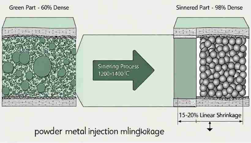
The Mathematics of Volume Loss
Deterministic Physics
| Initial Relative Density: | 60% |
| Final Relative Density: | 98% |
| Linear Shrinkage Calculation: | ~15% |
Formula: Volume Change ≈ (60/98)^(1/3) ≈ 0.85
Sources of Predictability: Why Shrinkage Stays at 15.2% ±0.1%
The shrinkage isn't remarkable; theconsistencyis. Three factors create this predictability.
1. Powder Characteristics
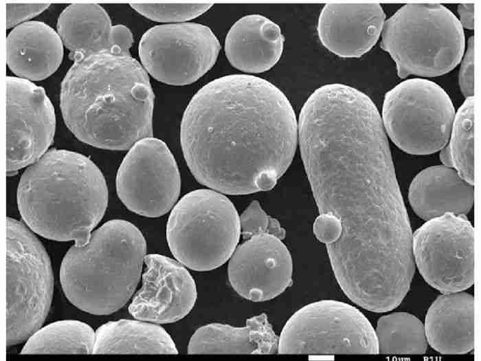
Uniform packing requires uniform particles. High-quality MIM powder specs are rigorous:
- Size:D50 = 8-12 μm (Strict distribution)
- Shape:Spherical (Aspect ratio < 1.5)
- Result:Uniform initial density throughout the mold.
2. Binder System Engineering
The binder controls packing uniformity and prevents segregation.
- Melt Flow Index (MFI):Ensures uniform loading.
- Thermal Expansion:Prevents stress during debinding.
- Result:The "Brown Part" retains the exact density map of the "Green Part."
3. Sintering Process Control
Temperature uniformity determines shrinkage uniformity. A 50°C delta causes warping.
- Temp Uniformity:±5°C across zone.
- Atmosphere:Prevents oxidation.
- Result:Shrinkage becomes a fixedmaterial property, not a variable.
How Predictability Enables Accuracy: The Compensation Mechanism
Now we reach the core insight: if shrinkage is always 15.2%, you don't fight it—you design for it.
1. The Compensation Calculation
Modern CAD/CAM software automates this, but understanding the math is critical. The shrinkage is a design parameter incorporated into your tooling.
Scenario: 316L Feedstock (Shrinkage: 15.2%)
2. Tolerance Achievement Through Repeatability
The critical point: Precision comes fromprocess repeatability, not just mold machining.
Tolerance Chain Analysis:
- Nominal Shrinkage:15.2%
- Process Variation:±0.1% (Range: 15.1% - 15.3%)
- Mold Dimension:11.79mm (Precision machined)
- Resulting Part Range:9.97mm to 10.03mm
- ✅ Final Tolerance: ±0.03mm (±0.3%)
3. Handling Complex Features
Because shrinkage is uniform, dimensional relationships (ratios) are preserved perfectly.
Mold Cavity (Before)
- Hole: 5.89mm
- Wall: 0.94mm
- Ratio:6.25
Finished Part (After)
- Hole: 5.00mm
- Wall: 0.80mm
- Ratio:6.25 (Preserved)
Isotropic Shrinkage: The Key to Geometric Complexity
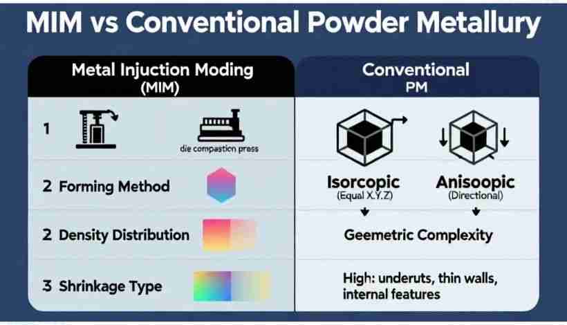
This is where MIM diverges from conventional powder metallurgy. MIM shrinkage happensin every direction simultaneously.
Why MIM Shrinkage is Uniform
| Process | Packing Method | Resulting Shrinkage |
|---|---|---|
| Conventional PM | Uniaxial Pressing (Top-Down) | Anisotropic(Density Gradients) |
| MIM | Fluid Injection (Hydrostatic) | Isotropic(Uniform X, Y, Z) |
What Isotropic Shrinkage Enables
Uniform shrinkage allows MIM to handle geometries that fail in other processes.
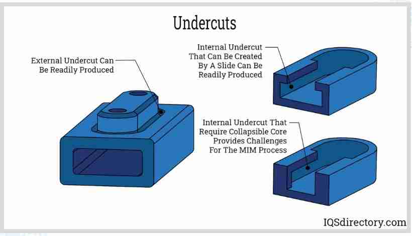
📐 Undercuts
A 45° angle remains exactly 45°. Since depth and width shrink proportionally, the angle geometry is locked in.
🧱 Thin Walls
Walls don't bow or taper. Because thickness and length shrink at the same 15.2% rate, parallel faces stay parallel.
⭕ Internal Channels
Circular channels stay circular. Isotropic shrinkage prevents the "ovalization" seen in other sintering methods.
🏗️ Multi-Level Features
Dimensional ratios between different heights (e.g., Boss vs Base) are preserved perfectly in the Z-axis.
When Predictability Breaks: Understanding Failure Modes
To appreciate why controlled shrinkage creates precision, we must examine what happens when control is lost.
1. Powder Inconsistency
The Cause:Bimodal particle distribution (e.g., 5μm mixed with 15μm) creating uneven packing density.
The Failure:Differential Shrinkage.High-density regions shrink less; low-density regions shrink more. Flat surfaces curve, and holes go out-of-round.
2. Temperature Variation
The Cause:A 30°C gradient in the furnace. The hot end shrinks before the cool end.
The Failure:Anisotropic Shrinkage.Internal stress pulls the part out of shape. Cylinders become ellipses. Geometric accuracy is destroyed.
3. Incomplete Debinding
The Cause:Residual binder trapped inside the part interferes with sintering.
The Failure:Density Gradients.The surface densifies, but the core has voids. The part looks fine but has hidden dimensional errors.
💡 The Lesson: Precision Requires Control
The 15.2% shrinkage isn't inherently precise. It becomes precise only when you control:
- ✅ Powder Quality
- ✅ Feedstock Mixing
- ✅ Packing Pressure
- ✅ Atmosphere
MIM is aprocess-intensivetechnology. Precision comes from rigorous control over each transformation step.
The Bottom Line: Engineered Transformation
Traditional Mindset (Machining/Casting)
"Dimensional change is a problem to minimize. We must remove material or stop shrinkage."
MIM Mindset
"Embrace the 15-20% volume reduction. Achieve precision by making that massive changepredictable."
This Paradigm Shift Enables:
- Complex Geometries:Mold intricate single-piece components that replace assemblies.
- Tight Tolerances:Achieve ±0.3-0.5% accuracy directly from the furnace.
- Reproducibility:Your 100,000th part shrinks exactly like your 100th part.
The Precision Mechanism: 5 Steps
Video: Animation of the complete MIM shrinkage transformation. Source: Nymus 3D
Frequently Asked Questions
Q: How do you compensate for 15% shrinkage in mold design?
A: You scale every dimension of the mold cavity by the inverse of the shrinkage factor. The Scaling Formula: Mold Dimension = Final Dimension / (1 - Shrinkage %). Example (15.2% Shrinkage): Mold = Final / 0.848. Note: Modern CAD software automates this scaling. Verify the factor via test coupons before cutting production steel.
Q: Does shrinkage affect all dimensions equally?
A: Yes. MIM shrinkage is Isotropic. Unlike press-and-sinter PM (which has directional density gradients), MIM's fluid injection creates uniform density. Shrinkage in X, Y, and Z axes is equal. Verification: Cubic test specimens should show axial variation within ±0.2%.
Q: Can you reduce shrinkage to <15% while maintaining precision?
A: Not without compromising physics. The 15-20% shrinkage is the necessary cost of eliminating the 40% porosity. Trying to reduce it forces a trade-off: Option A (Higher Green Density) requires less binder, with the consequence that feedstock becomes too viscous to inject into complex molds. Option B (Lower Final Density) leaves residual porosity, with the consequence that it degrades mechanical strength and dimensional stability.
Q: What happens if shrinkage varies between batches?
A: Batch-to-batch variation indicates process instability. If shrinkage drifts >±0.2%, dimensional tolerance fails. Root Cause Checklist: Powder Lot (Particle size distribution changes packing density), Feedstock Aging (Binder degradation alters flow/loading), Furnace Drift (Even 10-15°C shifts affect densification), and Debinding (Incomplete removal leaves residue).
Q: Why doesn't conventional PM achieve the same precision?
A: The difference lies in how density is distributed before sintering. In Conventional PM, the forming method is Uniaxial Die Compaction, which creates a state where gradients exist (high at punch face, low in center), leading to anisotropic shrinkage that distorts shapes. In MIM, the forming method is Fluid Injection Molding, which creates a uniform density state (hydrostatic pressure equalization), resulting in isotropic shrinkage that preserves geometry.
Custom MIM Parts from Emitech
Nanjing Emitech delivers MIM 316L, 17-4PH, 4340 and other materials from tooling through sintering and finishing. Custom MIM parts · MIM services · Request a quote
Last updated: 2026-06-23