
Key Takeaways
- Wall Thickness Uniformity:Maintaining0.8-2.5mmwalls is critical to prevent differential shrinkage and density gradients.
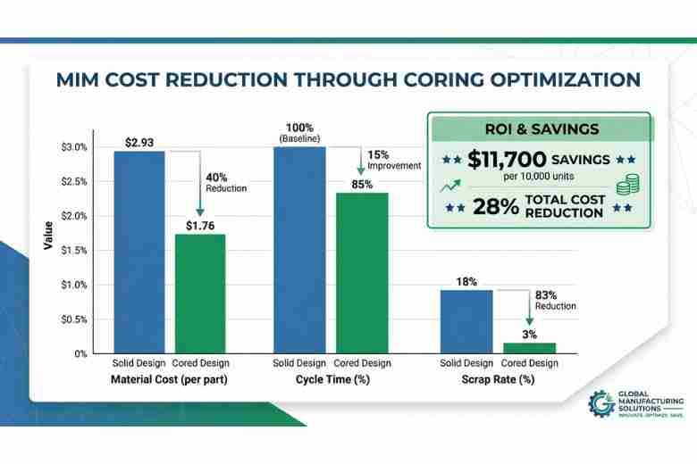
- Cost Reduction:Strategic coring can yield a total cost reduction of up to28%(material + yield).
- Density Control:Uniform walls keep density variation within<1%, ensuring mechanical integrity.
- Process Window:Optimized geometry requires adjusted parameters for injection (20-35 mm/s) and debinding.
- ROI Calculation:Break-even is typically achieved at moderate volumesdue to material savings.
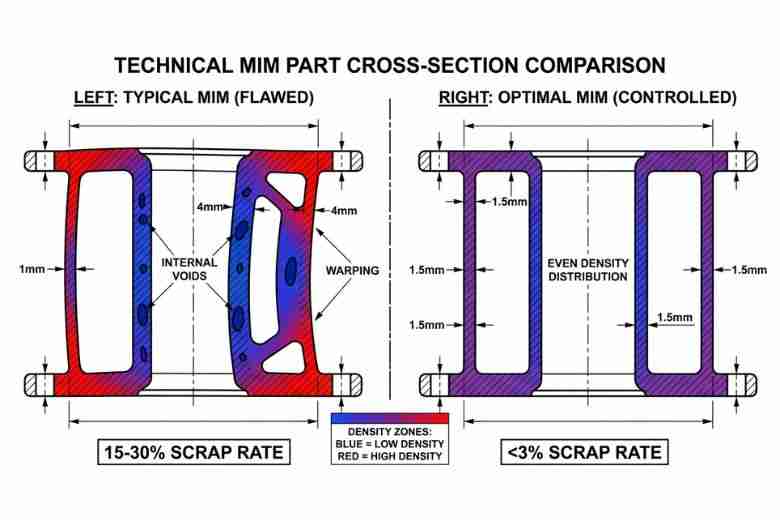
Wall thickness variation remains the dominant cost driver in MIM production, generating15-30% scrap ratesand extending cycle times by20-40%. Strategic coring design eliminates these losses while reducing feedstock consumption by40%. This analysis provides the design parameters and process controls required to achieve uniform density distribution.
The Economics of Wall Thickness Uniformity
Non-uniform wall thickness creates a cascade of manufacturing failures in MIM. When you design parts with thickness ratios exceeding3:1, you encounter:
Differential shrinkage:Sections>4mmshrink2-3%more than 1.5mm sections during sintering, creating dimensional distortion that exceeds ±0.3% tolerance windows.
Density gradients:Variations above0.2 g/cm³between thick and thin sections reduce mechanical properties by15-25%in critical stress zones.
Debinding defects:Binder removal rates scale with thickness squared (t²). A 4mm section requires16x longerdebinding than a 1mm section, creating internal voids when processed together.
The solution is maintaining uniform wall thickness at0.8-2.5mmthrough strategic material removal—coring.
Coring Design Parameters
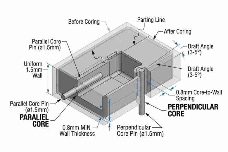
Parallel Coring (Along Parting Line)
- Core diameter:≥1.5mm for steel feedstocks, ≥2.0mm for tungsten alloys
- Draft angle:3-5°minimum for demolding
- Core-to-wall spacing:≥0.8mm to prevent breakthrough
- Surface finish:Ra 0.8-1.6 μm on core pin eliminates ejection marks
Perpendicular Coring (Across Parting Line)
- Alignment tolerance:±0.05mm between mold halves
- Shutoff design:0.2-0.3mm interference at core intersection
- Ejection force:Calculate as surface area × 12 MPa for 316L stainless
Critical Design Rule
Position cores to leave≥0.6mmwall surrounding the cavity. Complete breakthrough compromises handling during debinding when binder removal reaches60-80%and part strength drops to20-30%of sintered values.
Material savings calculationfor a typical component:
- Solid volume: 2,500 mm³
- Cored volume: 1,500 mm³
- Feedstock cost: quoted per project (316L at 7.8 g/cm³)
10,000-unit run:substantial material cost reduction
Add15% cycle time reductionand8% yield improvement:28% total cost reduction.
Process Window Adjustments
Uniform wall design narrows your process parameters. Target these specifications:
Injection Phase
- Fill velocity:20-35 mm/s(reduce 30% for walls <1.2mm)
- Pack pressure:50-90 MPa(adjust to achieve 60-62% solid loading)
- Mold temperature uniformity:±2°C across all cavities
Debinding Phase
Calculate hold time using:
Example: 2mm wall = (2)² × 2.5 =10 hours minimum
Sintering Phase
- Heating rate:3°C/minmaximum to 1380°C (316L)
- Temperature tolerance:±5°C in hot zone
- Final density:≥96% theoretical (7.5 g/cm³ for 316L)
Critical control point:Density variation across part must remain<1%to achieve ±0.3% dimensional tolerance.
Structural Efficiency Through Mass Reduction
Beyond simple coring, optimize geometry for maximum material removal:
Ribbed Structures
Replace solid sections with ribs when thickness>3mm:
- Rib thickness:0.6xnominal wall
- Rib height:≤3x rib thickness (prevents sink marks)
- Spacing:≥2x rib thickness between ribs
Result:35%mass reduction, 90% stiffness retention
Hollow Core Features
For components>15mmin any dimension:
- Wall thickness:1.0-2.0mmuniform
- Mass reduction:40-55%
- Shrinkage uniformity improvement:60%
Design verification:Run FEA to confirm stress concentration at hollow-to-solid transitions remains below0.7× yield strength.
Quality Acceptance Criteria
Establish these metrics for uniform-wall MIM parts:
| Parameter | Specification | Measurement Method |
|---|---|---|
| Density variation | <1% across part | Archimedes method, 5 zones |
| Wall thickness deviation | ±0.15mm | CMM, 10 points per feature |
| Surface roughness | Ra <1.6 μm | Profilometer, as-sintered |
| Hardness uniformity | <5 HRC range | Rockwell, 9-point grid |
Failure mode correlation:When density variation exceeds1.5%, you'll see12-18%reduction in fatigue life and8-15%loss in tensile strength.
Implementation Protocol
Before releasing MIM designs with coring features:
Step 1:Audit wall thickness
Identify all sections>2.5mm. Calculate thickness ratios between adjacent features.
Step 2:Design coring strategy
Target final wall thickness of1.2-2.0mm. Verify minimum0.6mmenvelope remains around all cores.
Step 3:Calculate shrinkage compensation
Apply16-18%linear compensation for steel alloys,19-21%for titanium. Use supplier-specific shrinkage data.
Step 4:Validate draft angles
Confirm≥3°on all surfaces perpendicular to parting line. Cored features require4-5°.
Step 5:Process simulation
Run mold-fill analysis to verify complete filling at35-55 MPainjection pressure. Check for weld lines at rib junctions.
Frequently Asked Questions
Q: What's the practical limit for wall thickness variation in a single part?
Maintain thickness ratio<2:1between thinnest and thickest sections. Above this ratio, you need staged debinding (thin sections first) or separated sintering cycles, which eliminates MIM's cost advantage. For parts with unavoidable thick sections, consider splitting the design into multiple components joined post-sintering.
Q: How do cored features affect dimensional tolerance?
Cored internal features typically achieve different tolerances than external surfaces:
- Internal cored dimensions:±0.12-0.15mm
- External surfaces:±0.08mm
- After 10,000+ cycles:±0.18mm (due to core pin wear)
Design for this degradation trajectory or establish preventive pin replacement schedules at8,000-12,000 shot intervals.
Q: Can you achieve tighter tolerances than ±0.3% with uniform walls?
Yes. With controlled wall thickness (±0.2mm variation) and optimized sintering profiles, you can reach±0.15%on features >10mm. This requires statistical process control on feedstock rheology and atmosphere purity >99.98%. Secondary operations like sizing or coining can further tighten tolerances to±0.05%on critical dimensions.
Q: Does coring weaken the part structurally?
Strategic coring maintains85-95%of solid section strength while reducing mass by 30-50%. The material removal is calculated to avoid critical stress zones identified through load path analysis.
Design Validation Protocol:
- Use FEA to verify maximum stress stays below0.65× yield strength
- Apply safety factor of1.5for static loads,2.0-2.5for cyclic loading
- Keep critical load paths and attachment points solid
- Validate with physical testing on first article inspection
Q: What's the ROI timeline for implementing coring in existing MIM parts?
Tooling modification costs vary widely per cavity depending on core complexity. Break-even analysis:
| Material savings per part: | Varies |
| Yield improvement: | 15% |
| Cycle time reduction: | 12-18% |
| Break-even volume: | 4,000-6,000 units |
| typical ROI timeline: within months |
Most production runs achieve positive ROI within months. For annual volumes exceeding50,000 units, payback period shortens significantly.
Custom MIM Parts from Emitech
Nanjing Emitech delivers MIM 316L, 17-4PH, 4340 and other materials from tooling through sintering and finishing. Custom MIM parts · MIM services · Request a quote
Last updated: 2026-06-26