
When your design requires undercuts, thin walls, and internal features, machining quotes force design compromises. Metal Injection Molding (MIM) eliminates this constraint while reducing per-part costs at production volumes above thousands of units.
What Are the Benefits of MIM Parts?
According to the Metal Powder Industries Federation (MPIF), MIM provides four quantifiable manufacturing advantages:
- Geometric complexity– Produces features impossible or cost-prohibitive to machine
- Production cost reduction– Achieves significant savings versus CNC at volume
- Material efficiency– Utilizes 95-98% of input material, substantially higher than typical machining yields
- Mechanical performance– Delivers 97-99% density with properties matching wrought metals
Below, we quantify each benefit with engineering data and real-world applications.
Understanding the MIM Process
[caption id="attachment_15069" align="aligncenter" width="780"]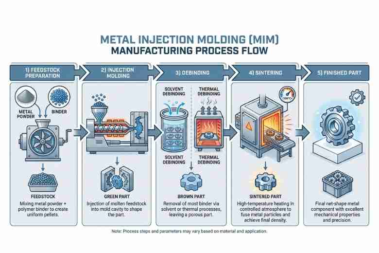 The MIM process transforms metal powder feedstock into high-density finished parts through injection, debinding, and sintering[/caption]
Benefit 1: Geometric Complexity Without Compromise
MIM replicates mold geometry with near-perfect fidelity, enabling features that require multiple setups or are impossible to machine.
Technical Capabilities
Wall thickness range:0.4-6mm without tooling limitations
[caption id="attachment_15070" align="aligncenter" width="780"]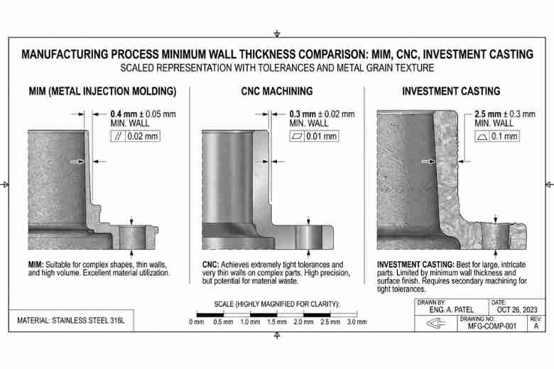 MIM enables 0.4mm walls with structural integrity, making it ideal for thin-walled complex components[/caption]
Real-world applications:
- Medical forceps: 0.5mm jaw thickness with integrated teeth geometry
- Smartphone hinge components: 0.6mm structural walls with bosses and snap features
- Watchband links: 0.8mm walls with internal locking mechanisms
Integrated features in single part:
- Internal threads (M1.0 and larger)
- Undercuts and perpendicular holes
- Multi-level geometries without secondary operations
- Knurling, logos, and surface textures replicated directly from mold
Part Consolidation Example
MIM can combine multiple machined components into a single monolithic part, eliminating assembly steps and joint-failure risks while reducing overall part count and development iterations.
Benefit 2: Economic Efficiency at Production Scale
MIM inverts traditional manufacturing economics by front-loading tooling investment and minimizing per-part variable costs.
Cost Structure Analysis
Tooling investment:Moderate to high upfront cost, complexity-dependent
Per-part cost composition:
- Material: 40-50%
- Sintering: 20-25%
- Debinding: 15-20%
- Labor: <10% (highly automated)
This structure means MIM becomes more economical as volume increases, while machining costs remain relatively constant.
Break-Even Analysis
MIM typically becomes economical at production volumes in the thousands of units annually, depending on part complexity, material cost, and tolerance requirements. Higher complexity and expensive alloys generally lower the break-even volume.
ROI Considerations
The break-even volume depends on tooling investment, per-part cost difference between MIM and CNC, and annual production volume. Complex geometries and expensive materials typically favor MIM at lower volumes.
Secondary Operation Savings
According to industry data from MPIF, MIM achieves significant labor cost advantages:
Near-net-shape dimensional accuracy:
- As-sintered tolerance: ±0.3-0.5% of nominal dimension
- Typical post-processing: <15% of parts require light finish machining
- CNC comparison: 100% of parts require multiple operations
Labor coefficient reduction:
- MIM cycle: 1 operator manages 4-8 presses producing 200-800 parts/hour
- CNC equivalent: 1 operator per machine producing 8-15 parts/hour for complex geometries
- Labor cost reduction: significant versus machining
Benefit 3: Material Utilization and Alloy Economics
MIM operates as a near-zero-waste process, making expensive alloys economically viable for high-volume production.
Material Efficiency Metrics
MIM material flow:
- Feedstock to finished part: 95-98% yield
- Runner/gate scrap: 2-5% (fully recyclable into new feedstock)
- Net material waste: <2%
CNC comparison for complex geometries (typical 4:1 buy-to-fly ratio):
- Bar stock to finished part: 25% yield
- Chip waste: 75%
- Chip recycling value: ~30% of virgin material cost
- Net material waste: >50% effective loss
[caption id="attachment_15077" align="aligncenter" width="780"]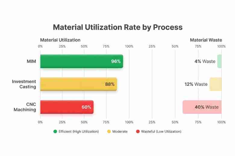 MIM achieves high material utilization, reducing waste compared with traditional machining[/caption]
High-Value Alloy Example
For expensive alloys such as titanium, MIM's high material utilization can significantly reduce net material cost compared with machining, especially at production volumes where tooling investment is spread across many parts.
Sustainability Impact
MIM can offer sustainability advantages over fully machined parts by reducing material waste, eliminating cutting fluids, and enabling internal recycling of feedstock scrap. Actual environmental impact depends on part geometry, material, production volume, and local energy mix.
Benefit 4: Mechanical Performance Matching Wrought Metals
MIM achieves high-density sintering that produces material properties equivalent to conventional wrought products, distinguishing it from other powder metallurgy processes.
Density and Microstructure
Sintering performance:
- Typical sintered density: 97-99% of theoretical
- Porosity: <1-3% (closed-cell, non-interconnected)
- Grain structure: Fine, uniform (ASTM grain size 8-10)
Comparison to other powder-based processes:
- Press-and-sinter PM: 85-92% density (interconnected porosity)
- Binder jetting: 90-95% density (requires infiltration or HIP)
- MIM advantage: Single-material composition without infiltration, true alloy properties
[caption id="attachment_15080" align="aligncenter" width="780"]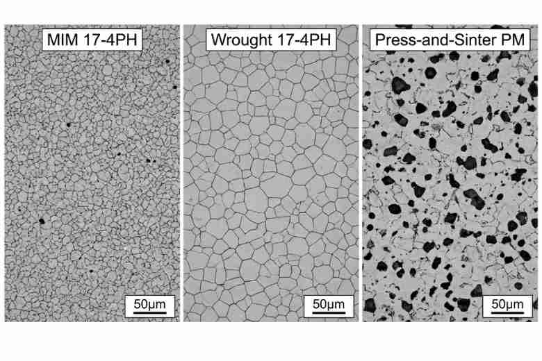 MIM microstructure (97-99% density) closely matches wrought metal, unlike traditional powder metallurgy (85-92%)[/caption]
Mechanical Property Data: 17-4PH Stainless Steel
According to MPIF Standard 35 and ASTM B883, MIM parts achieve the following properties:
| Property | MIM (H900 Condition) | Wrought (H900) | MIM as % of Wrought |
|---|---|---|---|
| Tensile Strength | 1,310 MPa | 1,340 MPa | 98% |
| Yield Strength (0.2%) | 1,240 MPa | 1,280 MPa | 97% |
| Elongation | 6% | 8% | 75% |
| Hardness | 42 HRC | 43 HRC | 98% |
| Density | 7.72 g/cm³ | 7.80 g/cm³ | 99% |
Engineering significance:MIM parts meet or exceed minimum mechanical requirements for applications originally designed for wrought materials.
Isotropic Properties vs. Additive Manufacturing
MIM microstructure advantage:Random powder particle sintering creates uniform properties in all orientations.
[caption id="attachment_15081" align="aligncenter" width="780"]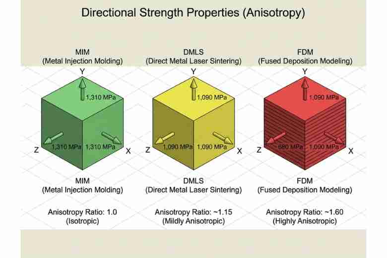 MIM delivers isotropic properties (1.00-1.02 anisotropy ratio) versus additive manufacturing's directional weakness (1.17-1.40 ratio)[/caption]
Directional strength comparison:
| Process | X-Direction | Y-Direction | Z-Direction | Anisotropy Ratio |
|---|---|---|---|---|
| MIM | 1,310 MPa | 1,310 MPa | 1,310 MPa | 1.00-1.02 |
| DMLS/SLM | 1,280 MPa | 1,280 MPa | 1,090 MPa | 1.17 |
| FDM Metal | 950 MPa | 950 MPa | 680 MPa | 1.40 |
Engineering benefit:No need to orient parts for load direction during design phase. MIM parts can be stressed equally in any direction without performance degradation.
Application Example: High-Cycle Fatigue Performance
MIM 316L sensor housings can meet typical automotive high-cycle fatigue requirements. Actual fatigue performance must be validated by testing production-representative samples under the specific loads, temperatures, and environmental conditions of the application.
Manufacturing Process Comparison Matrix
| Parameter | MIM | CNC Machining | Investment Casting |
|---|---|---|---|
| Optimal Volume | Thousands to millions of units | Low volumes | Moderate volumes |
| Cost per part (25K vol) | Lower at volume | Higher at volume | Moderate |
| Material waste | <5% | 40-60% | 10-15% |
| Minimum wall thickness | 0.4mm | 0.3mm | 2.5mm |
| Undercuts | Yes (mold-defined) | No (requires EDM) | Limited |
| Internal features | Yes | Limited | No |
| Density achieved | 97-99% | 100% | 98-99% |
| Typical tolerance | ±0.3-0.5% | ±0.025mm | ±1-2% |
| Surface finish (Ra) | 0.4-2.0 μm | 0.2-1.6 μm | 3.2-6.3 μm |
| Tooling cost | Moderate to high | Low to moderate | Moderate |
| Lead time | 12-14 weeks | 2-4 weeks | 10-12 weeks |
| Setup cost per run | Low (automated) | High (programming) | Moderate |
Color legend:Bold= Best-in-class for that parameter
[caption id="attachment_15082" align="aligncenter" width="780"]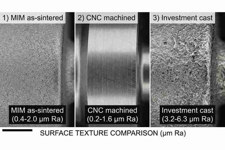 MIM as-sintered surface finish (0.4-2.0 μm Ra) approaches machined quality without secondary operations[/caption]
When These Benefits Matter Most
Ideal Application Scenarios
You maximize MIM benefits when your project has:
✓ Volume characteristics:
- Annual production in the thousands of units
- Multi-year production commitment (3+ years)
- Stable design (minimal revision frequency)
✓ Geometric requirements:
- Wall thickness between 0.4-4mm
- Undercuts or internal features
- Complex 3D geometry requiring 3+ machining setups
- Part consolidation opportunity (combining 3+ components)
✓ Material considerations:
- Expensive alloys (Titanium, Cobalt-Chrome, high-nickel)
- High material waste in current machining approach (>40%)
- Corrosion resistance or specific alloy properties required
✓ Performance requirements:
- Tolerance of ±0.3-0.5% acceptable (or willing to post-machine critical features)
- Mechanical properties matching wrought metals
- Isotropic strength required
Quick Decision Framework
[caption id="attachment_15083" align="aligncenter" width="780"]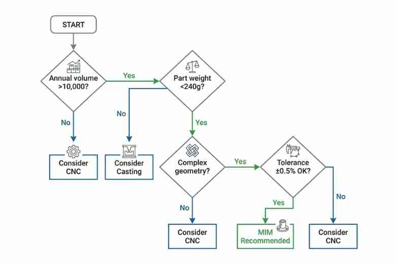 Use this decision framework to quickly assess if MIM is the optimal manufacturing process for your component[/caption]
Simplified decision path:
START↓Annual volume in the thousands of units? ──No──→ConsiderCNCorAdditive ↓ YesPart weight <240gANDsize<100mm? ──No──→ConsiderInvestment Casting ↓ YesComplex geometry (undercuts/internal features)? ──No──→EvaluateCasting ↓ YesTolerance ±0.5% acceptable? ──No──→ConsiderCNC + specifycriticalfeatures ↓ YesMIM HIGHLY RECOMMENDED ↓[Request Feasibility Analysis]Volume Threshold Calculator
Quick assessment formula:
Break-even volume = Tooling cost / (CNC cost - MIM cost)Actual break-even volume depends on part complexity, material cost, tolerance requirements, and annual production volume. Complex parts in expensive alloys typically reach break-even at lower volumes than simple parts in common materials.
Quality Considerations for MIM Parts
Inspection and Verification Methods
Dimensional verification:
- CMM measurement for critical features (±0.025mm capability)
- Optical comparison for complex geometries
- Statistical process control on key dimensions
Material property validation:
- Density measurement (Archimedes method per ASTM B962)
- Tensile testing (minimum 1 sample per 5,000 parts per MPIF-35)
- Hardness testing (100% inspection capability with non-destructive testing)
- Microstructure analysis (grain size, porosity assessment)
Common defects and detection:
- Surface porosity: Visual inspection + dye penetrant testing
- Dimensional distortion: CMM verification
- Incomplete sintering: Density measurement
- Contamination: Metallographic analysis
Acceptance criteria:
According to MPIF Standard 35, acceptance requires:
- Density ≥97% of theoretical
- Mechanical properties within ±5% of specification
- Surface porosity <ASTM E2109 Grade A3
- Dimensional conformance to drawing tolerances
Frequently Asked Questions
Q: What are the top 3 benefits of MIM for high-volume production?
- Cost reduction:Lower per-part cost versus machining at volumes above thousands of units, with tooling payback improving as volume rises
- Design freedom:Produce undercuts, thin walls (0.4mm minimum), and internal features impossible or cost-prohibitive to machine without assembly
- Material savings:95-98% utilization rate reduces expensive alloy costs significantly, which is critical for Titanium, Cobalt-Chrome, and specialty materials
Q: Can MIM parts handle structural loads like machined parts?
Yes. MIM parts achieve 97-99% theoretical density, providing tensile strength, hardness, and fatigue resistance within 95-100% of wrought material specifications according to MPIF Standard 35.
Unlike press-and-sinter powder metallurgy (85-92% density), MIM produces fully dense parts with closed-cell porosity that does not compromise mechanical performance. Additionally, MIM produces isotropic properties (uniform strength in all directions, anisotropy ratio 1.00-1.02) versus additive manufacturing's directional weakness (anisotropy ratio 1.05-1.40).
Validation:MIM parts routinely pass automotive, medical, and aerospace qualification testing designed for wrought materials.
Q: At what production volume does MIM become more economical than CNC machining?
Typical break-even range:Thousands of units annually, depending on part complexity.
Factors lowering break-even volume:
- Complex geometries requiring 4+ CNC setups
- Expensive materials (Titanium, specialty stainless steels)
- Tight tolerances on machined parts increasing cycle time
- High material waste ratio (>3:1 buy-to-fly)
Example:A part requiring 5 CNC operations may break even at lower volumes, while a simple 2-operation part may require higher volumes.
Use the formula:Break-even = Tooling cost ÷ (CNC cost per part - MIM cost per part)
Q: What materials are compatible with the MIM process?
MIM supports most ferrous and non-ferrous alloys used in engineering applications:
Stainless steels (most common):
- 316L, 17-4PH, 420, 440C
- Typical applications: Medical devices, firearms, consumer electronics
Tool steels:
- M2, D2, H13
- Applications: Cutting tools, wear parts, precision molds
Titanium alloys:
- Ti-6Al-4V (Grade 5)
- Applications: Medical implants, aerospace components
Specialty alloys:
- Cobalt-Chrome (CoCrMo) - biomedical
- Fe-Ni (Kovar) - electronics, thermal expansion matching
- Tungsten heavy alloys - radiation shielding, counterweights
Soft magnetic materials:
- Fe-Si, Fe-Ni alloys for electromagnetic applications
Q: How do MIM tolerances compare to precision machining?
Standard MIM as-sintered tolerances:±0.3-0.5% of nominal dimension
Example:
- 10mm feature: ±0.030-0.050mm
- 50mm feature: ±0.150-0.250mm
Precision CNC tolerances:±0.025mm (±0.001") achievable
Hybrid approach for best economics:
MIM for overall geometry + precision grinding/machining on critical datum surfaces. This approach still provides cost savings versus fully machined parts while achieving ±0.025mm where needed.
Critical tolerances achievable with post-processing:
- Grinding: ±0.013mm
- Wire EDM: ±0.025mm
- Coining/sizing: ±0.050mm on specific features
Q: What are the size and weight limitations of MIM?
Practical production limits (standard equipment):
- Maximum part weight: 240 grams
- Maximum dimension: 100mm
- Minimum wall thickness: 0.4mm (0.6-0.8mm recommended for consistent results)
- Maximum wall thickness: 6mm (optimal: <4mm to minimize sintering variation)
Parts exceeding these limits:
- 240g-500g: Possible with specialized large-format MIM equipment (limited suppliers)
500g: Investment casting or machining recommended
100mm: Consider casting or fabrication
Wall thickness considerations:
- Walls <0.6mm: Risk of warping during sintering
- Walls >6mm: Extended sintering time, potential for core porosity
- Optimal design: 0.8-3mm uniform wall thickness
Q: How long does MIM tooling development and production startup take?
Typical project timeline from design freeze to production:
| Phase | Duration | Activities |
|---|---|---|
| Mold design & approval | 2-3 weeks | CAD modeling, flow simulation, client review |
| Mold fabrication | 8-10 weeks | CNC machining, EDM, polishing, inspection |
| First article sampling | 2-3 weeks | Initial shots, sintering optimization |
| Process validation | 2-4 weeks | Dimensional verification, mechanical testing |
| Total | 14-20 weeks | Design freeze → production approval |
Comparison to other processes:
- CNC machining: 2-4 weeks (no tooling, direct from CAD)
- Investment casting: 12-16 weeks (similar tooling timeline)
- Die casting: 16-24 weeks (more complex tooling)
Expedited options:
- Soft tooling for prototypes: 50-100 parts in 6-8 weeks (moderate cost)
- Standard production tooling cannot be significantly accelerated due to mold quality requirements
Q: How do I get started with MIM for my project?
Step-by-step process:
1. Initial feasibility assessment (Week 1-2)
- Submit CAD file in STEP or IGES format
- Provide annual volume estimate and tolerance requirements
- Supplier reviews geometry, identifies potential issues
- Preliminary quote provided (tooling + piece price)
2. Design optimization (Week 2-4)
- DFM (Design for Manufacturing) review
- Wall thickness analysis and recommendations
- Gate location and runner system design
- Tolerance refinement for critical features
3. Prototype options (Week 4-12)
- Option A: 3D print for fit/function verification (low to moderate cost)
- Option B: Soft tooling for actual MIM parts (moderate cost for 50-100 parts)
- Option C: Use existing similar MIM part for material property validation
4. Production tooling (Week 12-26)
- Hard tooling fabrication (significant investment)
- First-article dimensional inspection
- Process validation and documentation
5. Production launch (Week 26+)
- Initial production run (typical MOQ in the thousands of units)
- Ongoing quality verification
- Volume ramp-up
What to prepare:
- CAD file with critical dimensions noted
- Annual volume forecast (3-year preferred)
- Material specification or performance requirements
- Tolerance requirements (general ±0.5% or specific callouts)
- Application description (helps identify testing needs)
Engineering Decision Summary
MIM delivers maximum value when your application requires:
✓ Production volume exceeding 10,000 units annually
✓ Complex geometry that eliminates 3+ machining operations
✓ Material waste reduction (especially with expensive alloys)
✓ Wall thickness requirements below 2mm
✓ Undercuts or internal features impossible to machine
✓ Part consolidation opportunity
Typical benefits at volume (reference case: complex stainless steel component):
| Benefit Category | Typical Impact |
|---|---|
| Cost reduction vs. CNC | Significant at production volumes |
| Material waste eliminated | Reduced versus machining |
| Assembly operations | Reduced from multiple components to one part |
| Lead time improvement | Shorter with no assembly queue |
| Carbon footprint | Typically lower due to less waste and no coolant |
| Tooling payback | Depends on volume and part complexity |
Next Steps: Get Your Custom MIM Analysis
Ready to evaluate MIM for your component?
We provide detailed feasibility assessments including:
- DFM (Design for Manufacturing) review with geometry optimization
- Break-even volume calculation specific to your part
- Cost comparison: MIM vs. your current process
- Material property validation for your application
- Production timeline and MOQ requirements
Submit for analysis:
- CAD file (STEP, IGES, or Parasolid format)
- Annual volume forecast
- Current manufacturing method and cost (if available)
- Critical performance requirements
Typical turnaround:3-5 business days for preliminary feasibility report
Technical Glossary
- Anisotropy Ratio:Measure of directional property variation. Ratio of 1.00 indicates perfectly uniform properties in all directions.
- As-Sintered:Parts in final condition after sintering without secondary machining or finishing operations.
- Binder:Thermoplastic or wax-based polymer mixed with metal powder to create injectable feedstock (typically 30-40% by volume).
- Buy-to-Fly Ratio:Ratio of starting material weight to finished part weight in subtractive manufacturing. 4:1 ratio means 75% material waste.
- Closed-Cell Porosity:Isolated internal pores that do not interconnect, maintaining mechanical properties (typical in MIM at <2% porosity).
- Debinding:Removal of polymer binder from molded "green" parts through solvent extraction, thermal degradation, or catalytic process.
- Feedstock:Homogeneous mixture of metal powder and binder prepared for injection molding.
- Green Part:Molded component before debinding, containing full binder content and oversize to compensate for sintering shrinkage.
- HIP (Hot Isostatic Pressing):Secondary process applying high pressure and temperature to eliminate residual porosity for critical applications.
- Isotropic Properties:Uniform mechanical properties in all directions, characteristic of randomly oriented sintered powder particles.
- Near-Net-Shape:Parts produced very close to final dimensions, requiring minimal or no secondary machining.
- Sintering:High-temperature process (typically 1250-1450°C) where powder particles bond through solid-state diffusion, achieving 97-99% density.
- Theoretical Density:Maximum achievable density for a given alloy with zero porosity (100% density).
- Wrought Material:Conventional metal product formed by rolling, forging, or extrusion from cast ingot. Used as reference standard for mechanical properties.
Precision Metal Parts from Emitech
Nanjing Emitech delivers MIM, CNC machining, and custom metal parts. MIM services · Request a quote
Last updated: 2026-06-24
Continue reading
- Metal Injection Molding vs. Stamping: Choosing the Best Process for Your Parts
- Metal Injection Molding with Hot Isostatic Pressing: Complete Engineering Guide to Achieving 99.9% Density
- Metal Powder Sintering Temperature Guide: Optimal Settings for Different Alloys
- MIM 304 Stainless Steel: High-Temperature, Oxidation, and Corrosion Resistance