
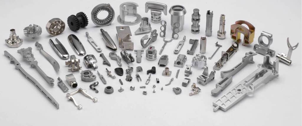
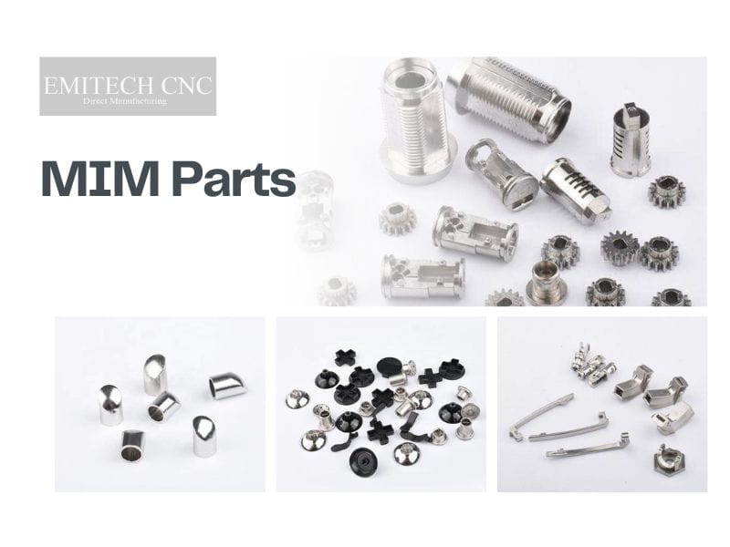
Metal injection molding (MIM) is a manufacturing process that produces small, complex metal parts by injecting a mixture of fine metal powder and polymer binder into a mold, then removing the binder and sintering the shaped compact into solid metal. It combines the shape freedom of plastic injection molding with the material performance of powder metallurgy, and it has become the standard production route for high-volume metal parts that are too intricate to machine economically and too demanding for die casting alloys.
What Is Metal Injection Molding?
MIM starts with feedstock: a carefully engineered blend of metal powder — typically gas-atomized particles under 22 µm — and a thermoplastic binder system that lets the mixture flow like plastic. That feedstock is injection molded into a cavity that is deliberately oversized, because the part will shrink predictably during sintering. The molded "green" part is then debound (the binder is removed by solvent, catalytic, or thermal means) and sintered at high temperature, where the metal particles diffusion-bond into a dense solid. The result is a near-net-shape metal component with properties close to wrought material, usually requiring little or no finishing.
Quick answer: Metal injection molding molds metal powder mixed with binder like plastic, then sinters the part to 95–99% dense metal. It is the economical choice for small (typically under 100 g), geometrically complex metal parts at volumes above roughly 10,000 pieces per year, with typical as-sintered tolerances of ±0.3–0.5% of the dimension.
The process was commercialized in the 1980s and is now standardized under MPIF Standard 35, which publishes minimum material properties for MIM alloys. Designers specify MIM where three conditions coincide: complex three-dimensional geometry (threads, cross-holes, thin walls, undercuts), small part size, and annual volumes that justify tooling. For an overview of where Emitech applies the process, see our metal injection molding services page.
The 4-Step MIM Process
Every MIM part travels the same four-stage route. Each stage has its own engineering controls, and most quality problems can be traced back to one of them:
| Step | What Happens | Key Controls |
|---|---|---|
| 1. Feedstock preparation | Fine metal powder is blended with a wax/polymer binder and granulated into moldable pellets | Powder size distribution (typically D90 < 22 µm), powder loading (~60% by volume), homogeneity |
| 2. Injection molding | Feedstock is injected into a hardened steel mold, forming a "green" part that is oversized by the shrinkage factor | Cavity scaled for 15–20% shrinkage, gate location, mold temperature, packing pressure |
| 3. Debinding | The binder is removed by solvent extraction, catalytic reaction, or controlled heating, leaving a fragile "brown" part | Heating rate, atmosphere, section thickness (thick walls debind slowly) |
| 4. Sintering | The brown part is heated to roughly 1,200–1,400 °C in vacuum or hydrogen atmosphere; particles diffusion-bond and the part densifies to 95–99% of theoretical density | Temperature profile, atmosphere purity, support/setter design, shrinkage consistency |
Two points matter for designers. First, shrinkage during sintering is large — typically 15–20% linear — but uniform and predictable, which is why MIM can hold tight tolerances despite it. Second, the molded part is fully formed before sintering, so geometry complexity costs almost nothing at the molding stage; complexity shows up in tooling cost, not unit cost. For a deeper walk through each stage, see the MIM process steps guide and our feedstock preparation page.
MIM Materials: From Stainless Steel to Tungsten
Almost any alloy that can be atomized into fine powder and sintered can be processed by MIM. Low-melting metals such as aluminum, zinc, and magnesium are the exception — those belong to die casting. The table below summarizes the common MIM material families, with typical property levels published in MPIF Standard 35:
| Material Family | Common Grades | Typical Tensile Strength | Typical Applications |
|---|---|---|---|
| Austenitic stainless | 316L, 304L | ~520 MPa, 40%+ elongation | Corrosion-resistant housings, fluid handling, watch cases, consumer goods |
| Precipitation-hardening stainless | 17-4PH (H900) | 1,170–1,310 MPa after aging | High-strength corrosion-resistant parts: firearms, aerospace, surgical tools |
| Low-alloy steel | MIM-4605, 8620, FN02/FN08 | Up to ~1,650 MPa quenched & tempered | Gears, lock hardware, power tool components, structural parts |
| Soft magnetic alloys | Fe-Si, Fe-50Ni | Magnetic performance is the spec | Relay cores, solenoid components, sensor yokes |
| Tool steel | M2, T42 | High hardness and wear resistance | Cutting edges, wear inserts, small tooling |
| Titanium | Ti-6Al-4V | ~900 MPa, biocompatible | Medical implants, aerospace brackets, premium watch parts |
| Tungsten heavy alloy | 90–97W-Ni-Fe | Density 17–18.5 g/cm³ | Radiation shielding, counterweights, balancing masses |
| Superalloy / cobalt-chrome | Inconel 718, Co-Cr F75 | High-temperature strength, wear | Turbocharger and aerospace hardware, medical/dental components |
Material selection follows the same logic as wrought alloys — corrosion, strength, wear, magnetics, biocompatibility — with one addition: sinterability. Alloys with stable oxide layers or extreme melting points need tighter atmosphere control. Grade-by-grade properties and selection logic are covered in the MIM materials guide and our material selection matrix.
Dimensional Capability: Tolerances, Shrinkage, and Size Limits
MIM's capability envelope is well documented across the industry. The numbers below are typical values designers can plan around, not best-case marketing figures:
| Attribute | Typical Value | Notes |
|---|---|---|
| As-sintered tolerance | ±0.3–0.5% of dimension | ±0.15–0.25 mm on a 50 mm feature; tighter with secondary machining (±0.01–0.02 mm) |
| Sintering shrinkage | 15–20% linear | Uniform and predictable; the mold cavity is scaled to compensate |
| Sintered density | 95–99% of theoretical | Delivers near-wrought mechanical properties; HIP available for critical parts |
| Wall thickness | 0.3–5 mm | 1–3 mm is the robust range; thin walls debind and sinter more uniformly |
| Part weight | ~0.1 g to 300 g | The economic sweet spot is under 100 g |
| Surface finish | Ra ~1–3 µm as-sintered | Polishing, blasting, plating, and coating all applicable |
The practical reading: MIM replaces machining where geometry is complex and tolerances are moderate, and it pairs naturally with light secondary machining for the few features that need tighter control. Detailed tolerance data by feature type is in our MIM tolerance guide; the physics behind the size envelope is covered under MIM size limitations.
MIM vs Machining, Casting, and Other Processes
MIM is rarely the only way to make a part — it is the cheapest way when the part is small, complex, and needed in volume. The honest comparison:
| Process | Best For | Where MIM Wins | Where the Other Process Wins |
|---|---|---|---|
| CNC machining | Prototypes, low volumes, very tight tolerances | Complex 3D geometry at volume; ~95% material utilization vs 15–25% machined from bar | Volumes below ~10k/year; tolerances tighter than ±0.05 mm throughout |
| Die casting | Al/Zn/Mg parts, larger sizes | Steel, stainless, titanium parts; much higher strength and temperature capability | Low-melting alloys; parts above ~300 g; thin-wall large housings |
| Investment casting | Complex shapes in almost any alloy | Tighter tolerances, better surface finish, faster cycle times, lower unit cost at volume | Larger parts; low-to-medium volumes; very thick sections |
| Conventional press-and-sinter PM | Simple 2D shapes, gears, bushings | True 3D geometry: undercuts, cross-holes, threads, thin walls | Simpler shapes at very high volume with cheaper tooling |
| Metal 3D printing | One-offs, internal channels, no tooling | Unit cost at volume; surface finish; throughput | Volumes below tooling payback; impossible-to-mold internal geometry |
For the two most common head-to-head evaluations, see our detailed breakdowns of MIM vs machining and MIM vs conventional powder metallurgy.
Design for MIM: 8 Rules That Prevent Expensive Mistakes
Most MIM cost and quality problems are designed in. These rules, applied before tooling is cut, prevent nearly all of them:
- Keep walls uniform. Aim for 1–3 mm throughout; abrupt thickness changes cause differential shrinkage and distortion during sintering. Core out thick sections rather than leaving solid mass.
- Design around 15–20% shrinkage. The mold cavity is scaled up to compensate, but shrinkage is only uniform when walls and powder loading are uniform.
- Budget ±0.3–0.5% as-sintered. Assign features that need tighter tolerances — precision bores, threads, sealing faces — to secondary machining instead of demanding them from the mold.
- Avoid sharp corners. Radii of 0.3–0.5 mm or more improve feedstock flow, reduce stress concentration, and extend mold life.
- Minimize undercuts and molded threads. Slides, lifters, and unscrewing cores are all possible, but each adds tooling cost. A molded core hole that is tapped afterward is often cheaper than a molded thread.
- Plan gate and ejector locations. Gate vestige and ejector marks are unavoidable; put them on non-cosmetic, non-functional surfaces.
- Provide a flat datum for sintering. Parts rest on setters in the furnace; a flat support face or a designed-in support strategy prevents slumping and distortion.
- Stay inside the size envelope. Parts under 100 g with walls of 0.3–5 mm hit the process sweet spot; larger or thicker parts need case-by-case feasibility review.
The full DFM checklist with feature-level guidance is in our MIM design guide.
Common MIM Failure Modes and How to Prevent Them
Understanding how MIM parts fail — in production and in service — is part of evaluating the process honestly:
- Debinding cracks and blisters. Caused by removing binder faster than it can diffuse out, especially in thick sections. Prevented by controlled debinding cycles and respecting wall-thickness limits.
- Distortion and slumping in sintering. Non-uniform walls shrink unevenly; unsupported spans sag at sintering temperature. Prevented by uniform wall design, proper setters, and flat staging surfaces.
- Dimensional scatter. Feedstock variability, mold wear, and furnace temperature gradients all show up as tolerance drift. Prevented by feedstock quality control and statistical process control on shrinkage.
- Carbon or oxygen contamination. Wrong furnace atmosphere changes chemistry and mechanical properties — too much carbon embrittles, oxidation weakens. Prevented by atmosphere and dew-point control.
- Weld lines and powder-binder separation. Poor gate placement or excessive injection shear creates weak knit lines or binder-rich/binder-poor zones. Prevented by gate design and feedstock quality.
- Residual porosity in fatigue-critical parts. Even 1–4% porosity reduces fatigue life. Prevented by sintering to the high end of the density range, or hot isostatic pressing for critical applications.
For a deeper treatment of sintering-stage defects specifically, see MIM sintering failure modes.
When Does MIM Make Economic Sense?
MIM economics are driven by one number: tooling cost amortized over volume. The typical industry pattern:
- MIM molds are hardened steel, multi-cavity tools, typically costing $8,000–$30,000+ depending on complexity, slides, and cavitation
- Below roughly 10,000 parts per year, tooling rarely pays back — machining or 3D printing usually wins
- The crossover against machining commonly falls in the tens of thousands of parts per year; above ~100,000 pieces annually, MIM is usually the lowest-cost route for small complex parts
- At volume, per-part cost reductions of 30–50% versus full machining are commonly reported, and material utilization rises from ~20% to ~95%
- Tooling lead time is typically 4–6 weeks; after that, molding cycles run in tens of seconds per shot
For detailed cost modeling, see the MIM cost guide, MIM tooling and mold design, and typical MIM lead times.
Working with Emitech on MIM Programs
Emitech is a MIM and CNC machining manufacturer with single-site production in Nanjing, China. Feedstock, tooling, molding, debinding, sintering, and secondary CNC operations are handled under one roof, so tolerance-critical features are finished in-house on the MIM blank. Upload a drawing for a free DFM review — our engineers respond with manufacturability feedback and a quotation within 24 hours. Learn more about our metal injection molding capabilities.
Frequently Asked Questions
Q: What is metal injection molding used for?
MIM is used for small, complex metal parts produced in volume: firearm components, surgical and dental instruments, automotive sensor housings and turbocharger parts, electronics connectors and hinges, lock hardware, watch cases, and power tool components. The common thread is geometry that would require multiple machining setups, combined with annual volumes that justify tooling.
Q: Is MIM the same as powder metallurgy?
MIM is a branch of powder metallurgy, but not the same as conventional press-and-sinter PM. Conventional PM compacts dry powder in a die, which limits parts to relatively simple 2D shapes. MIM mixes powder with binder and injection molds it, enabling true 3D geometry — undercuts, cross-holes, thin walls, and threads. See the full comparison in MIM vs powder metallurgy.
Q: How accurate is metal injection molding?
Typical as-sintered MIM tolerances are ±0.3–0.5% of the dimension — for example ±0.15–0.25 mm on a 50 mm feature. Features that need tighter control are finished by secondary machining, which routinely holds ±0.01–0.02 mm. Typical values by feature type are in our MIM tolerance guide.
Q: What is the difference between MIM and die casting?
Die casting injects molten metal and is limited to low-melting alloys — aluminum, zinc, magnesium. MIM molds metal powder with binder and then sinters it below the melting point, which works with steels, stainless, titanium, tungsten, and superalloys. MIM parts are far stronger and more heat-resistant; die casting wins for larger parts in light alloys.
Q: How much does MIM tooling cost, and when does it pay back?
A production MIM mold typically costs $8,000–$30,000 or more depending on complexity and cavitation. Tooling usually pays back from around 10,000 parts per year, and above roughly 100,000 pieces annually MIM is typically the lowest-cost route for small complex parts. See the MIM cost guide for worked examples.
Q: What materials can be used in MIM?
Most alloys that can be atomized and sintered: stainless steels (316L, 17-4PH), low-alloy steels (4605, 8620), tool steels, soft magnetic alloys, titanium, tungsten heavy alloys, superalloys, and cobalt-chrome. Low-melting metals such as aluminum, zinc, and magnesium are not MIM materials — they are die casting territory. Properties by grade are in the MIM materials guide.
Q: What size part is right for MIM?
The practical envelope runs from about 0.1 g to 300 g, with the economic sweet spot under 100 g. Wall thickness should stay between 0.3 and 5 mm. Larger parts are possible but need case-by-case feasibility review of debinding time, sintering support, and tooling cost.
Have a part that might fit MIM?
Upload your 2D/3D drawing. Our engineers will review geometry, material, and volume, and respond with a manufacturability assessment and quotation within 24 hours.
Precision Metal Parts from Emitech
Nanjing Emitech delivers MIM, CNC machining, and custom metal parts. MIM services · Request a quote
Precision Metal Parts from Emitech
Nanjing Emitech delivers MIM, CNC machining, and custom metal parts. MIM services · Request a quote
Last updated: 2026-06-24