
Key Takeaways
- ✓Volume Threshold:MIM becomes economically viable typically at annual volumes exceeding thousands of units.
- ✓Fatigue Limitation:Expect fatigue life below that of wrought steel due to residual porosity.
- ✓Carbon Control:Critical precision of±0.1%is required to maintain consistent hardness and strength.
- ✓Shrinkage:Design for uniform16-20%isotropic shrinkage during the sintering phase.
- ✓Cost Savings:Drastic reduction versus machining for complex geometries at high volume.
You're paying for a solid billet, machining away everything that isn't your part, and watching expensive tool steel turn into chips. For high-volume production, MIM typically offers substantial cost savings over machining—but only if your application fits the process. Here's how to make that determination.
Is MIM Right for Your Tool Steel Component? (30-Second Assessment)
Before investing time in this analysis, run this quick eligibility check:
| Criteria | Your Part | MIM Suitable? |
|---|---|---|
| Annual production volume > 10,000 units? | [ ] Yes / [ ] No | Required |
| Part weight between 5-100 grams? | [ ] Yes / [ ] No | Required |
| Complex geometry (undercuts, thin walls, integrated features)? | [ ] Yes / [ ] No | High value |
| Requires maximum fatigue life or impact toughness? | [ ] Yes / [ ] No | ❌ If yes, reconsider |
| Static loading or predictable wear application? | [ ] Yes / [ ] No | ✅ Ideal |
Score 3+ "Yes" answers (excluding fatigue question)?→ Continue reading
Score <3 or fatigue-critical?→ MIM likely not optimal for your application
Understanding Tool Steel MIM: What You're Actually Getting
Metal Injection Molding for tool steels is a four-stage powder metallurgy process that produces complex, hardened components (40-65 HRC) with95-99%theoretical density. The fundamental trade-off:you gain geometric freedom and material efficiency while accepting 1-5% residual porosity that limits fatigue performance.
Authoritative explanation from MPIF: Comprehensive overview of Metal Injection Molding (MIM) technology
The Core Process: Four Interdependent Stages
Each stage builds on the previous one. Defects introduced early propagate through the entire chain—there's no fixing a poorly mixed feedstock after molding.
Stage 1: Feedstock Preparation
You're mixing fine tool steel powder (4-25 μmparticle size) with a polymer binder system at60:40volumetric ratio. This precise ratio is non-negotiable: higher powder loading improves final density but increases viscosity; lower loading improves flow but increases shrinkage.
The binder serves as temporary structure—it must flow during molding, provide green part strength for handling, then decompose cleanly during debinding without leaving residue that affects carbon content.
Key specification:
- Powder particle size:4-25 μm(finer = better surface finish, higher sintered density)
- Powder-binder ratio:60:40by volume (±2% tolerance)
- Mixing uniformity: Critical—non-uniform distribution causes local density variations
Stage 2: Injection Molding
Your feedstock is heated to150-180°Cto melt the binder, then injected at800-2,500 barpressure into precision tooling. The resulting "green part" is16-20%oversized to compensate for sintering shrinkage.
Critical parameters:
- Melt temperature:150-180°C(varies with binder system)
- Injection pressure:800-2,500 bar
- Green part size:1.18-1.20×final dimension
- Handling strength: Fragile—requires careful processing
Stage 3: Debinding
This removes90-95%of the binder, transforming your green part into a porous "brown part" held together by residual backbone polymer. The process is delicate—too fast causes cracking from trapped gas pressure; incomplete removal causes carbon contamination during sintering.
Debinding methods and timeframes:
- Solvent debinding:24-48 hours(wax-based binders)
- Catalytic debinding:6-24 hours(fastest, requires specialized equipment)
- Thermal debinding:10-50 hours(slow, controlled atmosphere)
The brown part is extremely fragile—40% void space where binder was removed—and requires immediate transfer to sintering.
Stage 4: Sintering via SSLPS
This is where tool steel MIM becomes technically demanding. You're usingSuper-Solidus Liquid Phase Sintering (SSLPS)—heating above the solidus point but below liquidus to create a controlled liquid phase at grain boundaries.
How SSLPS works:
- Temperature rises to1,200-1,450°C(material-dependent)
- Partial melting occurs at grain boundaries (10-40%liquid phase)
- Liquid creates capillary forces that pull particles together
- Rapid densification occurs as pores collapse
- Part shrinks16-20%linearly as density reaches95-99%
The critical challenge:M2 high-speed steel has a sintering window of only ±15°C.Temperature too low? Insufficient densification. Too high? Part slumps and distorts. This narrow process window is why tool steel MIM requires expert process control.
Sintering parameters by common grades:
| Tool Steel Grade | Sintering Temperature | Sintering Window | Atmosphere | Typical Density |
|---|---|---|---|---|
| M2 (high-speed) | 1,260-1,280°C | ±10-15°C | N₂ or H₂ | ≥8.16 g/cm³ |
| H13 (hot work) | 1,200-1,260°C | ±20-30°C | N₂ or H₂ | ≥7.75 g/cm³ |
| S7 (shock-resisting) | 1,180-1,230°C | ±25-35°C | N₂ | ≥7.83 g/cm³ |
| D2 (cold work) | 1,230-1,280°C | ±15-20°C | Vacuum | ≥7.65 g/cm³ |
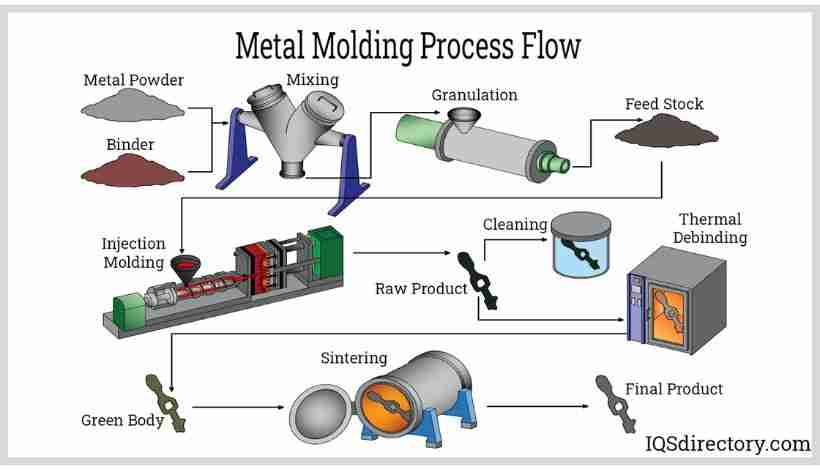
Four critical stages of MIM process: Feedstock preparation → Injection molding → Debinding → Sintering
💡 KEY TAKEAWAY
- Process is sequential: defects propagate forward
- SSLPS requires±10-30°Ctemperature control depending on alloy
- Brown part → sintered part involves16-20%dimensional reduction
- Total cycle time: 3-7 days from feedstock to sintered component
Tool Steel Selection: Matching Grade to Application
Not all tool steels process equally well via MIM. Your material choice involves balancing performance requirements against processability.
Common MIM Tool Steel Grades and Properties
High-Speed Steels: Maximum Wear Resistance
M2is the industry benchmark—despite its narrow sintering window, it's the most widely used MIM tool steel. After heat treatment, you achieve:
- Hardness:54-65 HRC
- Tensile strength: ≥1,400 MPa
- Applications: Cutting tools, wear plates, precision components
M4offers better toughness than M2 for applications with impact loading while maintaining comparable wear resistance.
T15delivers superior hot hardness—maintains cutting ability at elevated temperatures—but requires tighter process control due to higher tungsten content.
Hot Work Tool Steels: Elevated Temperature Performance
H13is your most forgiving option for MIM processing. Wider sintering window (±20-30°C) reduces development risk. After heat treatment:
- Hardness:48-53 HRC
- Tensile strength:1,950 MPa
- Yield strength:1,700 MPa
- Applications: Die casting dies, extrusion tools, hot forging dies
H11offers slightly higher hardness (53 HRC) with comparable toughness.
Cold Work Tool Steels: Dimensional Stability
D2(high-carbon, high-chromium) provides exceptional wear resistance with good dimensional stability during heat treatment. Achieves54-61 HRCwith tensile strength of1,900-2,200 MPa.
A2(air-hardening) offers better toughness than D2 when impact resistance matters, reaching57-62 HRC.
Shock-Resisting Tool Steels: Impact Applications
S7combines high impact toughness with good hardness (41-56 HRC). This grade is specifically chosen for components subjected to repeated high-energy impacts—like firearm strikers—where fracture resistance is critical.
Property Comparison: MIM vs. Wrought Tool Steel
Understanding the performance gap helps set realistic expectations:
| Property | MIM Tool Steel (Post-HIP + Heat Treat) | Wrought/Forged Tool Steel | Difference |
|---|---|---|---|
| Density | 95-99%theoretical | ~100% theoretical | -1-5% |
| Microstructure | Fine, equiaxed, isotropic | Elongated grain flow, anisotropic | Different optimization |
| Tensile Strength | 1,400-2,000 MPa | 1,500-2,100 MPa | 90-95% equivalent |
| Hardness | 40-65 HRC | 40-65 HRC | Equivalent |
| Fatigue Strength | Lower than wrought | Baseline (100%) | -10-15% |
| Impact Toughness | Significantly lower | Baseline (100%) | Lower |
| Wear Resistance | Excellent (fine carbides) | Excellent | Comparable or better |
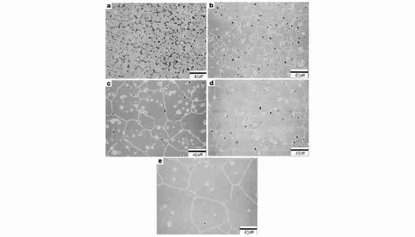
SEM microscopic analysis comparing microstructures of MIM sintered tool steel
Critical insight:The1-5%residual porosity in MIM components acts as microscopic stress concentrators. This is why fatigue strength is consistentlyLower than wrought equivalents even after HIP treatment. For static loading and wear applications, MIM performs comparably. For high-cycle fatigue or impact loading, this limitation is fundamental to the process.
💡 KEY TAKEAWAY
- H13 is easiest to process (widest sintering window)
- M2 offers best wear resistance but narrow process window
- S7 provides maximum impact toughness
- All MIM tool steels have10-15%lower fatigue strength vs. wrought
- Heat treatment is mandatory—hardness doubles from as-sintered state
Critical Process Challenges: What Actually Causes Failures
In practice, failures cluster around three technical challenges. Understanding these determines your success.
Challenge 1: Carbon Control (±0.1% Precision Required)
Tool steel properties are exquisitely sensitive to carbon content. A0.1%variation significantly affects hardness, strength, and wear resistance. During sintering at1,200-1,450°C, you're fighting competing chemical reactions:
Decarburization (carbon loss):
- Carbon + surface oxygen → CO gas
- Carbon + water vapor (H₂O in atmosphere) → CO + H₂
- Carbon + CO₂ (trace in atmosphere) → 2CO
Carburization (carbon gain):
- Residual binder decomposition products
- Methane in atmosphere → carbon absorption
- Graphite furnace elements → CO generation
Your control mechanisms:
- Atmosphere purity:Use high-purity hydrogen, nitrogen, argon, or hard vacuum (10⁻⁵ torr). Dew point must be <-40°C to minimize water vapor.
- Complete binder removal:Any residual binder becomes an uncontrolled carbon source. This is why debinding thoroughness is critical.
- Carbon compensation:Add0.05-0.15%graphite powder to feedstock to offset predictable losses from surface oxide reduction.
Failure mode:Miss target carbon by0.1%, and you'll see3-5 HRChardness variation between batches—making heat treatment unpredictable and properties inconsistent.
Challenge 2: Dimensional Control Through 18% Shrinkage
Your part undergoes massive dimensional change during sintering—16-20%linear shrinkage as void space is eliminated. Non-uniform shrinkage causes warping, distortion, and out-of-tolerance features.
Root causes of dimensional variation:
Gravity sag:At1,200-1,450°C, material yield strength drops dramatically. Unsupported features deform under their own weight.
- Solution: Orient parts to minimize unsupported spans; use custom setters
Friction constraints:Part contact with ceramic setter restricts shrinkage in contact area while free surfaces shrink normally.
- Solution: Use setters that shrink with the part; apply releasing agents
Thermal gradients:Non-uniform furnace heating causes sections to reach sintering temperature at different times.
- Solution: Specify maximum ±5°C thermal uniformity in hot zone
Green density gradients:Poor injection molding creates local density variations that translate to differential shrinkage.
- Solution: Optimize mold design, gate location, and process parameters
Modern approach:FEM simulation predicts final geometry, then inverse-calculates required pre-distorted mold shape. This can reduce tooling iterations and lead time.
Challenge 3: Defect Prevention Across Process Stages
Common defects and their root causes:
| Defect | Stage | Root Cause | Prevention |
|---|---|---|---|
| Warping/distortion | Sintering | Non-uniform wall thickness; thermal gradients | Maintain ±20% thickness uniformity; DfM review |
| Cracks | Debinding | Heating rate too fast; trapped gas pressure | Reduce heating rate to0.5-2°C/min |
| Blistering | Debinding | Residual binder pockets; incomplete removal | Extend debinding cycle; improve ventilation |
| Low density | Sintering | Temperature too low; insufficient hold time | Increase temperature 5-10°C; extend soak |
| Surface pitting | Sintering | Poor powder quality; contamination | Source high-purity powder; clean handling |
| Short shots | Molding | Melt temperature too low; insufficient pressure | Increase melt temp 10-20°C; raise pressure |
💡 KEY TAKEAWAY
- Carbon control requires±0.1%precision through atmosphere management
li>18% shrinkage demands uniform wall thickness and thermal control
- Simulation can reduce tooling iterations and associated cost
- Each defect traces to specific process parameter—systematic troubleshooting works
Post-Sintering Processing: Achieving Final Properties
Your as-sintered component does not have final properties. These post-processes are mandatory for critical applications, not optional enhancements.
Hot Isostatic Pressing (HIP): Eliminating Residual Porosity
What it does:Subjects your sintered part to inert gas pressure (100-200 MPa) at elevated temperature (1,000-1,200°C). The combination of heat and isostatic pressure collapses internal pores, increasing density from96-98%to99-100%.
Property improvements:
- Fatigue strength, impact toughness, and ductility all improve.
When to use HIP:
- ✅ Fatigue-critical applications (>10⁴ cycles)
- ✅ Impact-loaded components
- ✅ Maximum reliability requirements
- ❌ Simple wear applications (cost not justified)
Heat Treatment: Developing Hardness and Strength
Mandatory for all tool steel applications.Your as-sintered part is soft (28-35 HRC)—heat treatment develops the hardened martensitic structure that gives tool steels their performance.
Standard cycle:
- Austenitizing:Heat to950-1,150°C(grade-dependent) and hold for homogenization
- Quenching:Rapid cooling in oil, salt bath, or vacuum to form martensite
- Tempering:Reheat to150-650°Cto adjust final hardness and relieve stress
Property transformation example (H13):
- As-sintered:32 HRC, 950 MPa tensile strength
- After heat treatment:50 HRC,1,950 MPatensile strength
Secondary Machining and Finishing
MIM achieves ±0.3-0.5%dimensional tolerance as-sintered. If your application requires tighter tolerances, plan for secondary operations:
- Grinding:For critical dimensions needing ±0.01-0.025 mmtolerance
- Lapping:For precision mating surfaces (<0.5 μmRa finish)
- Drilling/tapping:For threads requiring Class 2 or better fit
Design to minimize post-processingby accepting as-sintered tolerances where possible.
💡 KEY TAKEAWAY
- HIP is non-negotiable for fatigue-critical applications
- Heat treatment is mandatory for all tool steels
- As-sintered tolerance ±0.3-0.5%; tighter specs require grinding
- Design to accept as-sintered capability on non-critical features
Industrial Applications: Where Tool Steel MIM Solves Technical Challenges
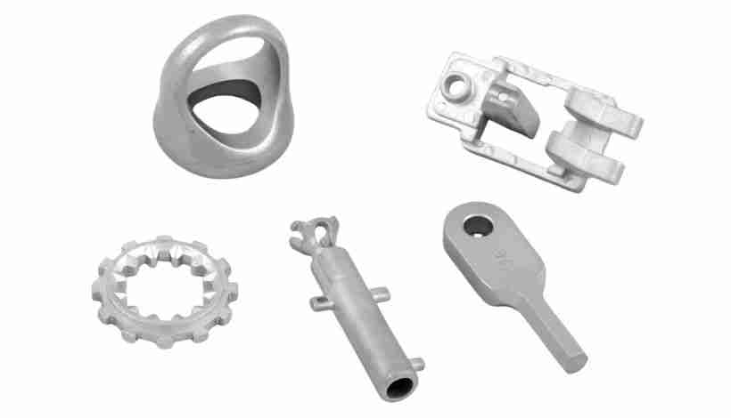
Complex tool steel components manufactured via MIM technology demonstrating precision geometric manufacturing capabilities
MIM dominates in applications where geometric complexity creates technical barriers for conventional manufacturing. Understanding these use cases clarifies the technology's capabilities.
Automotive: Turbocharger Vanes and Valve Systems
Variable geometry turbocharger vanesdemonstrate MIM's core strength—producing complex airfoil cross-sections with0.8-1.2mmwall thickness at1,000°Coperating temperature.
Technical challenge:Traditional investment casting struggles with thin-wall precision and surface finish. CNC machining requires 5-axis equipment with extended cycle times for each airfoil contour.
MIM solution:
- Material: Inconel 713 or H13 tool steel for thermal stability
- Wall thickness:0.8-1.2mmuniform throughout airfoil
- Surface finish:1.5-2.5 μmRa as-sintered (acceptable for aerodynamic function)
- Internal cooling passages: Moldable features impossible to machine
Key enabler:SSLPS allows near-full densification of high-temperature alloys while maintaining complex thin-wall geometry.
Hollow rocker armsfor variable valve timing exploit MIM's ability to create internal void spaces.
Technical challenge:Achieving weight reduction through internal cavities while maintaining structural integrity. Machining from solid stock wastes a large share of material.
MIM solution:
- Complex internal geometry formed during molding
- Wall thickness:2-3mmsurrounding internal cavity
- Weight reduction: Significant vs. solid machined equivalent
- Structural performance: Equivalent to machined part after HIP
Firearms: High-Impact Components
Modern firearms contain multiple MIM components where complex geometry meets impact loading requirements.
Example:S7 shock-resisting tool steel is often selected for impact-loaded firearm components. After sintering, HIP and heat treatment are used to maximize toughness and fatigue resistance.
Trigger mechanismsexploit feature integration—MIM produces trigger bodies with integrated sear surfaces, pivot holes, and spring retention features in one component vs. 3-4 machined parts requiring assembly.
Medical Devices: Miniaturized Surgical Instruments
Laparoscopic grasper jawsrequire complex articulation geometry at miniature scale.
Technical challenge:Jaw features include0.5mmthick gripping surfaces, pivot holes at 15° angles, serrated gripping teeth (0.3mmpitch), all in a component weighing 2-3 grams.
MIM solution:
- Material: 17-4PH stainless (biocompatible) or H13 (wear resistance)
- Integrated features: Pivot holes, serrations, and working surfaces formed in single operation
- Tolerance: ±0.2mmon critical pivot dimensions
- Surface finish:1-2 μmRa for smooth articulation
Key enabler:MIM produces these miniaturized complex geometries economically where micro-machining would require extensive setup time and specialized tooling.
Industrial Tooling: Injection Mold Components
Mold core with internal cooling channelsdemonstrate MIM's meta-application—using the technology to produce manufacturing equipment.
Technical challenge:Injection mold cycle time is limited by cooling efficiency. Internal cooling channels positioned close to mold cavity surface (2-3mm) dramatically improve heat removal.
MIM solution:
- Material: MIM-H13 for thermal conductivity and wear resistance
- Internal channel geometry:1.5-2.5mmdiameter serpentine passages
- Channel positioning:2-3mmfrom working surface
- Surface hardness:50-52 HRCafter heat treatment
Performance improvement:Mold cycle time can be reduced through enhanced cooling efficiency. These internal passages cannot be drilled economically—they must be cast (lower precision) or additively manufactured (higher cost per part).
Key enabler:The ability to form complex internal geometry through molding process, then achieve full density through SSLPS and HIP.
💡 KEY TAKEAWAY
- MIM solves specific technical challenges: thin walls, complex geometry, internal features
- Turbo vanes:0.8-1.2mmwalls at 1,000°C impossible to machine economically
- Firearm strikers: HIP mandatory for impact applications (eliminated crack initiation sites)
- Mold components: Internal cooling channels improve cycle time
Design for MIM (DfM): Technical Guidelines
Poor design is a leading cause of MIM program failures. These principles maximize manufacturability and minimize development iterations.
Rule 1: Maintain Uniform Wall Thickness (1-6mm)
This is your most critical design constraint.Thickness variation creates differential shrinkage during sintering, causing warping and internal stress.
Design targets:
- Ideal wall thickness:2-4 mm
- Minimum wall:1 mm(structural integrity)
- Maximum wall:6 mm(debinding limitation)
- Thickness variation: Within ±20% across entire part
For thick sections requiring structural strength:Core them out and use ribs instead of solid walls. A 10mm thick section should become a 3mm wall with 3mm ribs.
Failure mode:A part with 2mm walls transitioning to 6mm bosses will warp during sintering as the thick section shrinks more than thin sections.
Rule 2: Apply Generous Radii (Minimum 0.25mm)
Sharp internal corners serve as stress concentrators and crack initiation sites. They also impede feedstock flow during injection molding.
Design targets:
- Internal corners:0.5mmminimum radius, 1.0mm preferred
- External corners:0.25mmminimum radius
- Fillet transitions: Gradual tapers, not abrupt steps
Rule 3: Include Draft Angles for Ejection (0.5-2°)
Surfaces parallel to mold opening direction need slight taper to facilitate green part ejection without damage.
Design targets:
- External surfaces:1°minimum, 2° preferred
- Internal surfaces (holes, pockets):2°minimum, 3° preferred
- Deep features (depth >3× width): Increase draft to 3-5°
Rule 4: Leverage Complexity Integration
MIM's technical advantage is feature consolidation. Each integrated feature eliminates a secondary operation.
Features that form during molding:
- Internal and external threads (coarse pitch preferred)
- Through-holes and blind holes at any angle
- Undercuts (with side-action molds)
- Cross-holes and intersecting features
- Knurling, serrations, and surface textures
- Part numbers, logos, date codes (raised or recessed)
Design strategy:Ask "Can this be molded?" before defaulting to secondary operations.
Rule 5: Design for 18% Isotropic Shrinkage
Your mold cavity must be1.18-1.20×final part dimension. This is not a tolerance—it's a predictable, compensated shrinkage.
Critical considerations:
- Shrinkage is isotropic (equal in X, Y, Z directions)
- Tight tolerances require post-sintering machining
- Feature-to-feature dimensions within same cavity are more accurate than overall part dimensions
Common Design Mistakes and Corrections
| Design Error | Problem | Correction |
|---|---|---|
| 2mm wall adjacent to 8mm boss | Differential shrinkage → warping | Core out boss to 3mm wall with ribs |
| Sharp 90° internal corner | Stress concentration → cracking | Add0.5mmminimum radius |
| Zero draft angle on 10mm deep hole | Green part sticks in mold | Add 2° draft angle |
| Specifying ±0.05mmtolerance on 50mm dimension | Requires grinding (expensive) | Relax to ±0.15mm(0.3%) as-sintered |
| Designing for machining, then converting to MIM | Sub-optimal geometry | Redesign to integrate features |
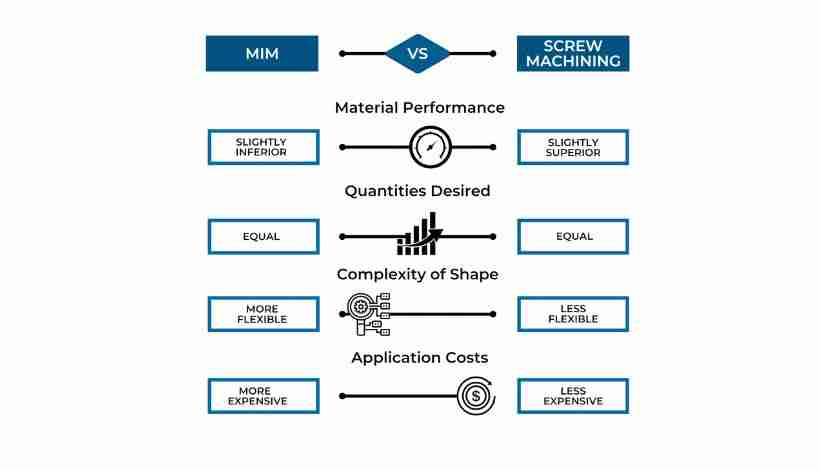
Manufacturing process comparison: MIM vs Machining vs Forging
DfM Checklist for Your Design Review
Before committing to tooling, verify:
- ☐ Wall thickness2-4mmwith <20% variation
- ☐ All internal corners have ≥0.5mmradii
- ☐ Draft angles 1-2° on all parallel surfaces
- ☐ Maximum wall thickness <6mm(debinding limit)
- ☐ Tolerances realistic for as-sintered capability (±0.3-0.5%)
- ☐ Features consolidated vs. machined equivalent
- ☐ No trapped volumes preventing binder removal
- ☐ Gate location optimized for flow and aesthetics
💡 KEY TAKEAWAY
- Uniform wall thickness (±20%) is non-negotiable for preventing warping
- Feature integration is where MIM creates technical advantage
- As-sintered tolerance is ±0.3-0.5%—design accordingly
- DfM review before tooling reduces costly iterations
Economic Feasibility: Understanding MIM's Cost Structure
Tool steel MIM requires higher upfront investment (tooling and process development) but lower per-part costs at volume. Economic viability depends on part complexity, annual volume, and the cost of alternative manufacturing methods.
Cost Framework
Non-Recurring Engineering (NRE):
- Precision multi-cavity tooling
- Process development and parameter optimization
- First-article inspection and qualification
Per-Part Variable Costs:
- Feedstock material
- Molding, debinding, and sintering processing
- Post-processing such as HIP and heat treatment
Break-Even Considerations
Break-even occurs when the cumulative savings in per-part cost offset the upfront NRE. Higher geometric complexity and larger annual volumes generally improve the business case for MIM relative to machining.
💡 KEY TAKEAWAY
- Upfront NRE requires sufficient volume to amortize
- Break-even volume depends heavily on part complexity and alternative-process cost
- Per-part cost advantage increases with geometric complexity
Implementation Strategy: Technical Development Path
Successful MIM implementation follows a structured technical development process.
Phase 1: Technical Feasibility (Weeks 1-3)
Objective:Validate technical viability
Key activities:
- Evaluate part geometry against DfM principles
- Assess loading conditions (static/dynamic, wear/fatigue)
- Select tool steel grade based on application requirements
- Engage MIM supplier for process assessment
Deliverable:Go/No-Go decision with technical justification
Phase 2: Design Optimization (Weeks 4-10)
Objective:Optimize geometry for MIM process
Key activities:
- DfM review: wall thickness, radii, draft angles
- Feature integration analysis
- Material specification and post-processing requirements
- Simulation analysis for shrinkage prediction
Deliverable:Frozen design optimized for MIM
Phase 3: Process Development (Weeks 11-24)
Objective:Establish robust manufacturing process
Key activities:
- Tooling design with shrinkage compensation (1.18-1.20×scale)
- Molding trials: optimize injection parameters
- Debinding/sintering optimization: establish thermal cycles
- Carbon control strategy development
- Tooling iteration if required (simulation reduces this to 0-1 iteration)
Deliverable:Validated process producing conforming parts
Phase 4: Qualification (Weeks 25-30)
Objective:Verify process capability and part performance
Key activities:
- Dimensional capability study (30-100 piece sample)
- Mechanical property testing (density, hardness, tensile strength)
- Application-specific validation (wear, fatigue, impact as required)
- Microstructural analysis
Deliverable:Qualification report demonstrating conformance
Phase 5: Production (Weeks 31+)
Objective:Stable production at target volume
Key activities:
- Statistical process control implementation
- Process parameter documentation
- Production ramp and yield monitoring
Deliverable:Production parts meeting specifications
Total timeline:several months from start to production (reduced with simulation)
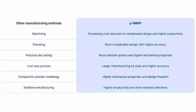
Comprehensive comparison matrix of manufacturing methods: MIM, Machining, Casting, and Forging
💡 KEY TAKEAWAY
- Development requires30-34 weeksfor complex tool steel components
- Simulation reduces timeline by eliminating tooling iterations
- Phased approach with clear technical milestones minimizes risk
Frequently Asked Questions
Q: Can MIM tool steel components match forged part performance?
For static loading and wear applications, yes—after HIP and proper heat treatment, you achieve 90-95% of forged properties. However, fatigue strength remainsLower than wrought equivalents due to residual porosity (even after HIP). Impact toughness is lower than forged parts.
Critical decision point:If your application involves high-cycle fatigue (>10⁴ cycles) or impact loading, conduct application-specific testing to validate performance. MIM may not be optimal for extreme dynamic loading scenarios.
Q: What tolerances can I realistically achieve with tool steel MIM?
As-sintered capability:
- Overall dimensions: ±0.3-0.5%of nominal dimension
- Example: 50mm dimension → ±0.15-0.25mmtolerance
- Feature-to-feature (within same mold cavity): ±0.1-0.2%
- Surface finish:0.8-3.2 μmRa
Post-grinding:
- Precision ground surfaces: ±0.01-0.025 mm
- Lapped surfaces: <0.5 μmRa finish
Design recommendation:Specify ±0.3%tolerance for as-sintered features to avoid grinding costs. Reserve tight tolerances for critical mating surfaces only.
Q: Why is carbon control so critical in tool steel MIM?
Tool steel hardness, strength, and wear resistance depend directly on carbon content. Typical specification: 0.4-2.0% carbon with ±0.1%tolerance.
Problem:During sintering at1,200-1,450°C, competing reactions either add or remove carbon:
- Decarburization: Carbon reacts with oxygen/water vapor
- Carburization: Residual binder decomposes into carbon
Impact of poor control:0.1%carbon variation causes:
- 3-5 HRChardness variation between batches
- Inconsistent heat treatment response
- Unpredictable wear performance
Solution:High-purity atmosphere (H₂, N₂, Ar, or vacuum), complete binder removal, and carbon compensation in feedstock.
Q: Should I use HIP for my application?
Use HIP when:
- ✅ Fatigue life is critical (>10⁴ cycles)
- ✅ Impact loading occurs
- ✅ Maximum reliability required
Skip HIP when:
- ❌ Static loading only
- ❌ Wear is primary failure mode
- ❌ Cost-sensitive application
Property improvements with HIP:
- Density:96-98%→ 99-100%
- Fatigue strength:+15-30%
- Impact toughness:+20-40%
Q: Can I convert an existing machined part directly to MIM?
Usually not without redesign. Parts designed for machining rarely optimize for MIM's capabilities.
Required changes:
- Add draft angles (1-2°) for mold release
- Adjust wall thickness uniformity (±20%)
- Account for18%shrinkage in all dimensions
- Eliminate sharp internal corners (add radii)
Opportunity:Redesigning for MIM allows feature integration—combine what were 3-5 machined components into one MIM part.
Recommendation:Engage your MIM supplier during design phase for DfM review before finalizing geometry.
Q: How long does process development take?
Standard timeline: 30-34 weeksfrom design freeze to production qualification
Breakdown:
- Tooling design and fabrication: 8-12 weeks
- Molding trials and optimization: 2-4 weeks
- Debinding/sintering development: 2-4 weeks
- First article testing: 2-3 weeks
- Production ramp: 2-4 weeks
Acceleration:Simulation reduces timeline by 4-8 weeks (eliminates tooling iterations)
Q: What post-processing operations are required?
For critical tool steel applications:
| Operation | Purpose | When Required |
|---|---|---|
| HIP | Eliminate porosity | Fatigue-critical applications |
| Heat treatment | Develop hardness | All tool steel applications (mandatory) |
| Grinding | Tight tolerances ±0.01mm | Critical dimensions only |
| Lapping | Ultra-smooth surfaces | Precision mating surfaces |
Q: How does MIM compare to 3D metal printing?
MIM advantages:
- Surface finish:1-3 μmRa vs. 10-25 μm Ra
- Mechanical properties: Consistent vs. orientation-dependent
- Production speed: Much higher for MIM at volume
3D printing advantages:
- No tooling investment
- Extremely complex internal geometries
- Ideal for prototypes (<100 units)
Decision framework:
- Prototype/low volume (small quantities): 3D printing
- Production (higher volumes, typically thousands of units per year): MIM
💡 KEY TAKEAWAY
- Process development:30-34 weeks(reduce with simulation)
- HIP mandatory for fatigue applications
- Design for MIM from start—don't convert machined designs
- Break-even typically occurs at production volumes in the thousands of units
Conclusion: Tool Steel MIM Technical Assessment
Tool Steel MIM is a specialized powder metallurgy process that solves specific manufacturing challenges—producing geometrically complex components in high-hardness materials where conventional manufacturing is technically difficult or economically unfeasible.
Core technical capabilities:
- Four-stage process achieves95-99%density via SSLPS
- Produces complex geometries with0.8mmminimum walls
- Achieves40-65 HRCafter heat treatment
- Enables internal features impossible to machine
Fundamental limitations:
- 1-5%residual porosity limits fatigue strength toLower than wrought
- Narrow sintering window (±10-30°C) demands process expertise
- Requires production volumes in the thousands of units per year minimum for economic viability
- Not optimal for extreme impact or high-cycle fatigue applications
Technical decision framework:
Use MIM when:
- ✅ Geometric complexity creates machining barriers (thin walls, undercuts, internal features)
- ✅ Production volume>10,000 units/yearsustained
- ✅ Static loading or predictable wear application
- ✅ Part consolidation opportunity exists
Avoid MIM when:
- ❌ Maximum fatigue life required
- ❌ Simple geometry economical to machine
- ❌ Low production volumes
- ❌ Extreme impact loading
Critical success factors:
- Material selection:Match tool steel grade to application and process window
- DfM principles:Uniform wall thickness ±20%, proper radii and draft
- Process control:Carbon management ±0.1%, thermal uniformity ±5°C
- Post-processing:HIP for fatigue-critical, heat treatment mandatory for all
The technology has matured significantly. With proper material selection, simulation-guided design, and post-processing, you can produce complex tool steel components that were previously impossible or economically unfeasible.
For applications where geometric complexity meets hardness requirements at production volume, Tool Steel MIM delivers a compelling technical solution.
Precision Metal Parts from Emitech
Nanjing Emitech delivers MIM, CNC machining, and custom metal parts. MIM services · Request a quote
Last updated: 2026-06-24