
Metal injection molding typically becomes favorable at tens of thousands of parts annually, with low per-part cost at scale but significant upfront tooling. Metal 3D printing has no tooling investment but higher per-part cost regardless of volume. This crossover point shifts dramatically with part complexity: simple designs favor MIM at lower volumes, while topology-optimized geometries can justify AM economics even at 100,000+ units.
This guide deconstructs both technologies from process fundamentals through economic modeling, helping you identify the optimal manufacturing path for your specific application.
Understanding the Core Technologies
Metal Injection Molding: A Four-Stage Process
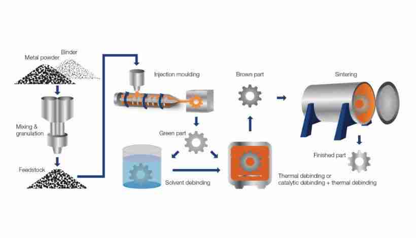
Metal Injection Molding combines injection molding with powder metallurgy through four sequential stages. Understanding these stages reveals MIM's core constraints and capabilities.
Feedstock Preparation
Fine metal powder (<20 microns) blends with polymer binders at approximately 60:40 ratio by volume, creating feedstock that flows like plastic during injection. Powder particle size distribution directly impacts final sintered density and part quality.
Injection Molding
Feedstock enters conventional injection molding machines, filling hardened steel molds under high pressure. The "green part" output is oversized by ~20% to compensate for sintering shrinkage. Multi-cavity molds produce multiple parts per cycle, enabling the high throughput that drives MIM's economics.
Debinding
Two-stage binder removal: solvent extraction dissolves primary components, thermal processing removes remaining polymer. The resulting "brown part" is extremely fragile but ready for sintering. Design constraint: sections >12.5mm thick risk incomplete debinding.
Sintering
Parts densify in controlled-atmosphere furnaces at 1,350-1,400°C (for stainless steel), shrinking 15-20% isotropically to final dimensions. Properly sintered parts achieve 96-99% theoretical density with mechanical properties comparable to wrought materials. Critical advantage: batch processing—thousands of parts sinter simultaneously, creating powerful economies of scale.
Metal 3D Printing: Three Distinct Approaches
Metal additive manufacturing encompasses multiple technologies with fundamentally different physics and economics. Understanding these distinctions is critical for accurate cost modeling.
Powder Bed Fusion (DMLS/SLM)
Powder Bed Fusion represents the most mature metal AM technology. A high-power laser (200-1000W) selectively melts metal powder particles layer by layer (20-50 microns thick) in an inert atmosphere.
Key characteristic: PBF melts metal during the build process through serial, high-energy input. This creates parts with >99.5% density and fine-grained microstructures often exceeding wrought material properties. However, this architecture fundamentally limits throughput and drives high per-part costs.
PBF requires support structures anchoring parts to prevent thermal warping, managing heat gradients, and providing foundation for overhangs. Support removal adds significant post-processing time and cost.
Metal Binder Jetting
Binder Jetting uses fundamentally different physics. Printheads deposit liquid polymer binder onto metal powder beds, "gluing" particles together layer by layer—no melting occurs during printing.
The output is a green part requiring debinding and sintering, identical to MIM's backend process. This shared metallurgical foundation positions binder jetting as "MIM without the mold," leveraging the same efficient batch sintering.
Binder jetting trades some density (95-98% with 0.2-2% residual porosity) for dramatically higher throughput. Multiple printheads deposit binder simultaneously, and hundreds of parts print in a single build for batch sintering. This enables direct competition with MIM at intermediate volumes (10,000-100,000 parts).
Bound Powder Extrusion
Bound Powder Extrusion uses metal-polymer composite filament—essentially MIM feedstock in wire form—extruded through a heated nozzle layer by layer. The printed green part undergoes the same debinding and sintering as MIM and binder jetting.
Advantage: lower equipment entry cost than PBF, and safer handling versus loose powder systems. Tradeoff: lower resolution and longer build times.
Note: Direct Energy Deposition (DED) exists for large parts and repairs but targets applications outside this comparison's focus on small, complex components.
Why Cost Structures Differ Fundamentally
The economic divide stems from when and how energy is applied. PBF melts metal during printing—a serial, energy-intensive operation limiting throughput and creating high per-part costs regardless of volume.
MIM, binder jetting, and BPE separate shaping from densification. Shaping requires relatively low energy, while the energy-intensive sintering is a batch process—thousands of parts densify simultaneously. This batch architecture explains MIM's economies of scale: sintering cost per part decreases as furnace capacity fills, while PBF costs remain essentially constant.
Design and Geometric Freedom: A Comparative Analysis
Designing for MIM: Managing Molding and Sintering Constraints
MIM design rules derive from injection molding mechanics and sintering physics. Mastering these constraints enables cost-effective production of complex parts at scale.
Wall Thickness Uniformity
Maintain uniform wall thickness between 1-6mm. Non-uniform sections create differential cooling during molding and non-homogeneous shrinkage during sintering, causing warping and voids. Sections >12.5mm risk incomplete debinding—core out thick sections to maintain uniformity.
Gate Location and Parting Lines
Position gates at the thickest section for balanced flow. Gate location, parting lines, and ejector pin marks are permanent features—locate them on non-critical surfaces where they won't affect function or appearance.
Sintering-Induced Distortion
Design for gravity effects at 1,350°C. Unsupported features like cantilevers will sag when semi-solid. Friction between part and ceramic setter creates drag impeding uniform shrinkage. Provide stable, flat resting surfaces. Complex geometries may require custom ceramic setters, adding cost.
Draft Angles: Often Optional
Unlike plastic molding, MIM often doesn't require draft angles—wax in feedstock acts as natural mold release. However, deep features or high aspect ratios benefit from 0.5-2° draft to reduce green part damage risk.
Stress Concentration Management
Avoid sharp internal corners. Specify 0.4-0.8mm fillets and radii to improve flow, reduce sintering stress, and extend part fatigue life.
Designing for Metal AM: Leveraging Geometric Freedom
Additive manufacturing inverts traditional design constraints—complexity becomes an asset rather than a cost driver.
Support Strategy in PBF
Part orientation balances multiple factors: minimizing support volume (reduces cost and post-processing), optimizing build time (Z-height), and aligning grain structure with primary load paths. Design with support removal accessibility in mind—internal channels must allow support extraction.
Topology Optimization and Lightweighting
AM enables performance-driven design unconstrained by manufacturability. Define loads and constraints in optimization software to generate organic structures using minimum material. Aerospace applications can achieve meaningful weight reduction through geometries that are difficult to mold or machine.
Part Consolidation
Redesign multi-component assemblies as single monolithic parts, eliminating fasteners, welds, and assembly operations while potentially improving performance by removing stress-concentrating interfaces. Consolidating assemblies can yield net savings by eliminating assembly labor, fasteners, and associated quality issues.
Internal Features and Conformal Design
Create internal channels impossible with conventional manufacturing. Design conformal cooling channels following complex contours for dramatically improved thermal efficiency. Integrate internal lattice structures to reduce weight while maintaining structural performance.
Post-Processing Accessibility
Design for mandatory post-processing from the start. Internal channels require sufficient diameter and self-supporting geometry for complete powder removal. Surfaces requiring tight tolerances must be accessible for subsequent machining. A printable but unfinishable part is useless.
The Economic Complexity Inversion
In AM, complexity is essentially free—print cost depends on volume (material) and height (time), not geometric intricacy. A complex hollow lattice can cost less than a solid cube because it uses less material.
In MIM, complexity increases mold cost. Features requiring side-actions or complex cores add significant tooling cost. Design strategy: actively add value through AM complexity (lightweighting, consolidation) while pursuing elegant simplicity in MIM to minimize tooling cost.
Material Capabilities and Mechanical Performance
Process selection ultimately depends on whether resulting parts meet performance requirements. Material properties are not just a function of alloy composition but are fundamentally shaped by the manufacturing process.
Material Portfolio Comparison
MIM Materials
MIM supports a broad, well-established material portfolio with particular strength in ferrous alloys:
- Stainless steels: 316L (corrosion resistance), 17-4PH (strength), 420/440C (hardness)
- Low-alloy steels: 4605, 8620 (cost-effective structural applications)
- Tool steels: M2, H13, D2 (wear resistance)
- Specialty alloys: cobalt-chrome, nickel superalloys, tungsten carbide
Metal AM Materials
PBF supports diverse high-performance alloys:
- Aluminum: AlSi10Mg (lightweight structural)
- Titanium: Ti6Al4V (aerospace, medical implants)
- Nickel superalloys: Inconel 718, 625 (high-temperature aerospace)
- Stainless steels: 316L, 17-4PH, 15-5PH
- Cobalt-chrome: CoCrMo (medical, dental)
Sinter-based AM (binder jetting, BPE) often leverages the same MIM-grade powders, enabling direct material property comparison and smoother technology transition paths.
Density and Microstructural Integrity
MIM:Properly executed MIM achieves 96-99% theoretical density. The small residual porosity (<3%) consists of microscopic voids that can initiate fatigue cracks under cyclic loading. For critical applications, Hot Isostatic Pressing (HIP) post-processing can achieve 100% density.
PBF:DMLS/SLM achieves >99.5% density, often exceeding investment casting and approaching wrought material density. The rapid melting and solidification creates extremely fine grain structures.
Binder Jetting:Typically achieves 95-98% density with 0.2-2% residual porosity. This slight porosity can reduce fatigue strength in high-cycle applications but is acceptable for most industrial uses.
Comparative Mechanical Properties: 17-4PH Stainless Steel (H900)
| Property | MPIF Standard 35 | MIM (Actual) | Sinter-Based AM (Actual) |
|---|---|---|---|
| Density (g/cc) | 7.5 | 7.58 | 7.63 |
| Hardness (HRC) | 33 | 41.0 | 38.5 |
| 0.2% Yield Strength (ksi) | 158 | 163.0 | 160.7 |
| Ultimate Tensile Strength (ksi) | 172 | 179.6 | 180.6 |
| Elongation (%) | 6 | 14.0 | 10.3 |
Key observations:Both MIM and sinter-based AM meet MPIF standards with nearly identical strength values. The primary difference is ductility—MIM shows 36% higher elongation (14.0% vs. 10.3%).
Surface Finish: Engineering Property, Not Cosmetic Feature
MIM:As-sintered surface roughness of Ra 0.8-1.6μm represents near-net-shape quality. Many MIM parts require no secondary finishing.
PBF:As-built surface of Ra 6-15μm shows visible layer lines and partially sintered powder particles. This rough surface acts as stress concentrators, significantly reducing fatigue strength.
Binder Jetting:As-sintered Ra 4-8μm—smoother than PBF but rougher than MIM.
For applications involving cyclic loading (automotive, aerospace, medical devices), post-processing AM parts to achieve smooth surfaces isn't optional—it's mandatory for structural integrity.
Economic Analysis: Cost Structure and Break-Even Modeling
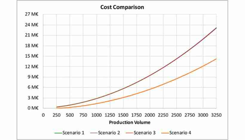
Cost analysis requires understanding the fundamentally different economic models underlying each technology.
Capital Investment Requirements
MIM Tooling
Mold costs range from a few thousand dollars for simple single-cavity tools to tens of thousands for complex multi-cavity tools. This upfront investment creates a fixed cost that must be amortized across production volume. Tooling cost scales directly with geometric complexity. Features requiring side-actions, cams, or complex cores add significant tooling cost per feature.
Metal AM Equipment
- PBF systems: high capital investment
- Binder jetting: moderate capital investment
- BPE: lower capital entry point
Per-Part Cost Dynamics
MIM Cost Structure
After tooling investment, per-part costs are exceptionally low due to:
- Lower feedstock cost per kilogram for common alloys
- Highly automated processes requiring minimal labor
- Fast cycle times (10-60 seconds per shot for multi-cavity molds)
- Batch sintering spreading furnace costs across thousands of parts
AM Cost Structure
Per-part costs remain relatively constant regardless of volume:
- Higher metal powder cost with strict particle requirements
- High machine capital cost amortized across part production
- Significant energy consumption per part
- Mandatory skilled labor for setup, monitoring, and extensive post-processing
The Economic Crossover Point
The break-even volume where MIM total cost equals AM total cost typically occurs at20,000-30,000 parts annually. However, this crossover point is dynamic, not fixed.
Representative Cost Comparison (Small Complex Part)
Exact total-cost comparisons depend on part geometry, material, tolerances, supplier pricing, and post-processing. As a general rule, AM is more economical at low volumes, while MIM becomes favorable at higher annual volumes once tooling is amortized.
Total Cost of Ownership: Beyond Per-Part Economics
MIM Lock-In Effect:Tooling creates design lock-in. Once mold tooling is invested, design changes are expensive (often thousands of dollars) and time-consuming (6-12 weeks). This creates opportunity cost in fast-moving markets.
AM Flexibility Premium:Higher per-part costs buy design flexibility. You can improve designs between production runs with zero penalty. In dynamic markets (consumer electronics, medical devices), this agility can provide returns exceeding the per-part cost difference.
Lead Time Analysis
Prototyping and Development Phase
- AM:1-5 days from CAD to finished part
- MIM:10-20 weeks for tooling development before first part production
Production Throughput
Once tooling is complete, MIM delivers dramatically higher throughput. Cycle times of 10-60 seconds per shot enable thousands of parts daily. A single MIM machine can match the output of hundreds of 3D printers.
The Post-Processing Time Factor
AM lead time calculations must include extensive post-processing: stress relief heat treatment, support removal, wire EDM to separate from build plate, CNC machining critical features, surface finishing. This workflow can consume a large share of total fabrication time.
Strategic Application Mapping
High-Volume Mass Production: MIM's Domain
Automotive Powertrain Components
Turbocharger components like variable nozzle turbine vanes exemplify MIM's value proposition. These aerodynamically complex parts require high-temperature superalloy materials (Inconel) and tight tolerances (±0.015mm) at volumes exceeding one million units annually.
MIM can provide cost savings versus alternative manufacturing while achieving the dimensional precision and material properties required. Other applications include transmission components, fuel system parts, and sensor housings.
Medical Device Mass Production
Surgical instruments (forceps, scissors, retractors) and orthodontic brackets represent ideal MIM applications: small, geometrically complex, requiring biocompatible materials (316L stainless steel), and produced in millions of units.
Complex, Low-Volume, High-Value: AM's Territory
Aerospace Lightweighting and Consolidation
Topology-optimized structural components like brackets, hinges, and mounting hardware demonstrate AM's unique value. Engineers define load paths and let optimization software generate organic structures using minimum material.
Topology-optimized AM brackets can achieve significant weight reduction in aerospace applications. Weight savings in aerospace have direct economic value through reduced fuel consumption over the part's service life.
Patient-Specific Medical Devices
Custom implants (cranial plates, spinal implants, joint replacements) manufactured from patient CT scan data represent applications impossible for MIM. Each part is unique, eliminating any possibility of tooling amortization.
AM enables mass customization: the economic model works because each patient requires a different part. Beyond implants, AM accelerates medical device innovation by eliminating MIM's long tooling lead times.
Rapid Tooling and Hybrid Strategies
AM serves as complementary technology to conventional manufacturing. 3D printed injection mold inserts with conformal cooling channels—impossible to create by drilling—improve injection molding cycle efficiency, reducing cycle time and improving part quality.
The Bridge Production Strategy
A powerful hybrid approach leverages AM for initial product phases:
- Prototype and validatewith AM (weeks, not months)
- Launch with AM productionto serve initial market demand
- Refine designbased on real-world use
- Transition to MIMonce design stabilizes and volume justifies tooling
This strategy is particularly seamless with sinter-based AM (binder jetting, BPE) since materials and sintering metallurgy match MIM, ensuring AM prototype properties predict final MIM production part performance.
Decision Framework and Implementation
Critical Evaluation Questions
Systematically evaluate your project against these factors:
Production Volume
- <1,000 units: AM clear choice
- 1,000-10,000: AM likely optimal; consider binder jetting
- 10,000-50,000: Detailed economic modeling required
- >50,000: MIM strongly favored unless geometry demands AM
Geometric Complexity Assessment
- Can the design leverage AM's unique capabilities?
- Is the geometry moldable or does it require impossible features?
- Does complexity justify AM's higher per-part cost?
Design Maturity
- Stable, frozen design → MIM investment justified
- Iterative development → AM maintains flexibility
- Uncertain market demand → AM reduces tooling risk
Timeline Requirements
- Need parts in 1-2 weeks → AM only option
- 3-6 month development cycle → AM advantageous
- Long-term program (1+ years) → MIM timeline acceptable
Quantitative Decision Matrix
Score your project (1-5 scale) on each criterion:
| Factor | Weight | MIM Favorability | AM Favorability |
|---|---|---|---|
| Annual volume >50,000 | 25% | High volume (5) | Low volume (1) |
| Complex/impossible geometry | 20% | Simple (1) | Complex (5) |
| Design stability (5+ years) | 15% | Stable (5) | Iterative (1) |
| Time-to-market urgency | 15% | Patient (1) | Urgent (5) |
| Tooling capital availability | 15% | Available (5) | Limited (1) |
| Maximum density critical | 5% | Critical (5) | Less critical (1) |
| Surface finish requirements | 5% | Critical (5) | Can post-process (3) |
Implementation Considerations
For MIM Implementation:
- Invest in Design for Manufacturing early
- Plan for 12-20 week lead time before production
- Factor mold maintenance into long-term cost models
- Consider multi-cavity tooling strategy to maximize throughput
For AM Implementation:
- Build post-processing capabilities or partner with service bureaus
- Invest in design optimization software
- Establish powder handling and safety protocols
- Plan for iterative design improvement
- Consider sinter-based AM if planning eventual MIM transition
Future Developments Affecting Current Decisions
Sinter-based AM (binder jetting, BPE) is maturing rapidly, pushing the economic crossover point from 20-30K toward 50-100K parts. Post-processing automation is expected to reduce AM labor costs over the next several years.
Implications for current decisions:These trends favor starting with AM for design flexibility, knowing MIM transition remains viable as volumes scale. The hybrid prototype-with-AM, produce-with-MIM workflow becomes increasingly seamless as sinter-based technologies converge with MIM's metallurgy.
Key near-term developments: automated powder removal and support structure systems, advanced sintering simulation software for predicting shrinkage in complex geometries, and expanded material portfolios for both technologies.
Frequently Asked Questions
Q: How much does MIM cost per part compared to 3D printing?
For a representative small complex part, MIM has low per-part cost at high volume but requires significant upfront tooling. PBF 3D printing has high per-part cost with no tooling. Binder jetting falls between. The crossover typically occurs at tens of thousands of parts for typical geometries.
Q: Can I start with 3D printing and transition to MIM later?
Yes, this is increasingly common, especially using sinter-based AM (binder jetting, BPE) which shares MIM's sintering metallurgy. This enables accurate prediction of final MIM part properties from AM prototypes. The strategy de-risks product development by validating market demand before tooling investment.
Q: How do mechanical properties actually compare for the same material?
For 17-4PH stainless steel, MIM and sinter-based AM achieve nearly identical strength (180 ksi ultimate tensile strength) but MIM shows approximately 35% better ductility (14% vs. 10% elongation). PBF processes can exceed wrought material strength but may exhibit directional properties. Surface finish significantly impacts fatigue life—MIM's smoother surface (Ra 0.8-1.6μm) outperforms as-built AM (Ra 6-15μm).
Q: What production volume makes MIM economically viable?
Economic viability depends heavily on part complexity. Simple geometry with lower tooling investment breaks even at lower volumes. Complex geometry with higher tooling investment requires higher volumes to break even. MIM becomes strongly favorable above tens of thousands of units annually. Below 10,000 parts, AM maintains economic advantage.
Q: How long does it actually take to get parts from each process?
AM: 1-5 days from CAD file to finished parts (including post-processing). MIM: 10-20 weeks for tooling development, then 2-4 weeks for first production parts. Once in production, MIM produces thousands of parts daily with 10-60 second cycle times, while AM build times range from hours to days per build batch.
Q: Which technology produces stronger parts?
Both MIM and PBF achieve excellent strength. MIM produces isotropic properties comparable to wrought material (96-99% density). PBF achieves >99.5% density with fine-grained microstructure that can exceed wrought material strength. Binder jetting achieves 95-98% density, slightly lower but acceptable for most applications. The key differentiator is surface finish impact on fatigue—MIM's superior as-sintered surface provides better fatigue performance.
Q: What are the size limitations for each process?
MIM optimal range: 0.1-100g parts, feasible up to 400g. Typical maximum dimension around 100mm. AM accommodates larger parts within build chamber constraints: PBF typically 100-500mm cube, binder jetting up to 800mm. However, MIM is specifically optimized for small, complex parts where it offers maximum economic benefit.
Q: Can design changes be made after production starts?
MIM: Design changes require mold modifications or new tooling—expensive (often thousands of dollars) and time-consuming (6-12 weeks). This creates design lock-in once tooling is commissioned. AM: Design changes are instantaneous—simply update the CAD file with zero cost penalty. This makes AM ideal for iterative development while MIM suits stable designs with long lifecycles.
This technical analysis provides engineering and manufacturing decision-makers with quantitative frameworks for process selection. Specific applications require detailed cost modeling based on actual part geometry, production volume forecasts, and material requirements.
Precision Metal Parts from Emitech
Nanjing Emitech delivers MIM, CNC machining, and custom metal parts. MIM services · Request a quote
Last updated: 2026-06-24
Continue reading
- Types of Sintering Processes: From Solid-State to Spark Plasma (SPS)
- Understanding Internal Gears: A Comprehensive Guide to Their Design and Function
- Small Gear Materials Selection: Complete Guide to Steel, Aluminum & Advanced Composites
- What Are MIM Parts? A Complete Technical Guide to Metal Injection Molding