
IN713C Metal Injection Molding (MIM) is a manufacturing process for nickel-based superalloys designed for extreme heat environments exceeding 900°C. MIM delivers high material utilization and superior fatigue resistance through a fine-grained structure, though it inherently offers lower creep life compared to traditional investment casting.
Key Takeaways
- Fatigue vs. Creep Trade-off:Fine-grained MIM structure excels in high-cycle fatigue but performs poorly in high-temperature creep applications (>800°C).
- Al/Ti Oxide Challenge:High aluminum content creates stable oxides; requires strict oxygen control (<400 ppm) to prevent prior particle boundary failures.
- Material Savings:MIM offers near-net-shape efficiency, typically reducing waste compared to CNC machining for expensive superalloys.
- HIP Requirement:Hot Isostatic Pressing is mandatory for aerospace integrity, specifically at1180°Cto avoid incipient melting.
- Aerospace Validation:IN713C MIM stator vanes have been evaluated for safety-critical aerospace hardware.
IN713C MIM delivers high material utilization and potential cost reduction for complex components—if your application is fatigue-limited, not creep-limited. This analysis explains the fundamental trade-off.
The Critical Performance Trade-Off You Must Understand
Before you commit to tooling investment or supplier qualification, understand this: MIM processing fundamentally changes IN713C's microstructure and performance profile compared to conventional casting. You're not simply choosing a different manufacturing method—you're selecting a different material performance envelope.
Fine-Grained Structure: The Double-Edged Sword
MIM produces a characteristically fine-grained microstructure (20-50 μm grain size) while investment casting produces coarse grains (>500 μm to millimeter scale). This single microstructural difference creates a direct performance trade-off that dictates your application suitability.
Where MIM IN713C excels:
Your fine-grained MIM structure provides superior performance from room temperature to approximately 800°C. Research data from aerospace manufacturers demonstrates:
- Yield strength: 734 MPa (MIM) vs. 689-817 MPa (cast)
- Ultimate tensile strength: 968 MPa (MIM) vs. 758-952 MPa (cast)
- Fatigue resistance: Significantly superior rotating bending fatigue life compared to cast and HIPed material
The absence of large casting defects (shrinkage cavities, inclusions) and the uniform, fine-grained structure make MIM inherently resistant to fatigue crack initiation. Aerospace evaluations of IN713LC MIM stator vanes have demonstrated this advantage in high-cycle fatigue environments.
| Property | MIM IN713C | Cast IN713C | Advantage |
|---|---|---|---|
| Grain Size | 20-50 μm | >500 μm | Cast (for creep) |
| Yield Strength (RT) | 734 MPa | 689-817 MPa | Comparable |
| Fatigue Life | Superior | Baseline | MIM |
| Creep Resistance (>800°C) | Lower | Higher | Cast |
| Microstructural Uniformity | Excellent | Variable | MIM |
Where MIM IN713C fails:
Above 800°C under sustained load, creep becomes your limiting failure mode—and here, MIM's fine-grained structure is fundamentally detrimental. The high density of grain boundaries provides extensive pathways for grain boundary diffusion and sliding. Research confirms stress exponent n = 2.72, indicating grain boundary diffusion creep as the dominant mechanism.
Your coarse-grained cast material, with minimal grain boundary area, demonstrates markedly superior creep resistance. This performance gap cannot be eliminated through process optimization alone—it requires post-HIP grain growth heat treatments that partially reverse the fine-grained structure.
Application Decision Framework
Select MIM when:
- Primary failure mode is high-cycle fatigue or thermal fatigue
- Service temperature predominantly <850°C
- Complex geometry with undercuts, thin walls, internal features
- Production volume >10,000 units/year
- HIP post-processing is acceptable
Avoid MIM when:
- Long-term creep rupture life is critical design requirement
- Sustained operation >850°C under constant tensile load
- Simple geometry easily produced by casting or machining
- Low production volume (<5,000 units/year)
This trade-off is not negotiable—it's fundamental materials science. Your manufacturing decision must align with your component's dominant failure mechanism.
Why IN713C Challenges MIM Processing
IN713C's composition creates specific processing challenges that distinguish it from more forgiving stainless steels or even other nickel superalloys like IN718.
The Aluminum-Titanium Oxide Problem
Your alloy contains approximately 6 wt% aluminum and 0.8 wt% titanium—far higher than IN718 (0.5% Al, 0.9% Ti). These elements form the strengthening γ'-Ni₃(Al,Ti) phase essential for high-temperature performance, but they're also highly reactive with oxygen.
During powder atomization, the high surface-area-to-volume ratio creates extensive opportunity for oxide formation. Even with argon atomization, you cannot completely eliminate surface oxidation. These Al₂O₃ and TiO₂ films are thermodynamically more stable than the Cr₂O₃ or Fe₂O₃ oxides formed on stainless steels.
During sintering, these oxides decorate prior particle boundaries (PPBs), physically hindering atomic diffusion necessary for metallurgical bonding. The consequence: PPBs become preferential crack initiation sites under fatigue loading.
| Oxide Type | Gibbs Free Energy at 1260°C | Stability | Implication for MIM |
|---|---|---|---|
| Al₂O₃ | -1100 kJ/mol | Extremely Stable | Very difficult to reduce; persists at PPBs |
| Cr₂O₃ | -540 kJ/mol | Moderately Stable | Partially reducible in vacuum |
| FeO | -240 kJ/mol | Relatively Unstable | Easily reduced; minimal PPB issues |
This thermodynamic reality explains why IN713C requires oxygen control <500 ppm while 316L stainless tolerates <1000 ppm. The aluminum oxide simply won't reduce during normal sintering atmospheres.
The Narrow Sintering Window Challenge
IN713C exhibits a uniquely steep temperature-density relationship:
- 1250°C: 96.5% theoretical density
- 1260°C: 98.6% theoretical density
- 1270°C: 99.2% theoretical density
This 20°C window producing 2.7% density change reflects the high γ'-forming element content affecting solidus and liquidus temperatures. The combined Al+Ti content (~8 wt%) creates a narrow temperature range between achieving sufficient diffusion for densification and approaching incipient melting of the γ-γ' eutectic (liquidus ~1260°C).
| Alloy | Sintering Window | Al+Ti Content | Process Sensitivity |
|---|---|---|---|
| IN713C | 20°C | ~8 wt% | Very High |
| IN718 | 50°C | ~5.5 wt% | Moderate |
| 316L Stainless | 80°C | 0 wt% | Low |
This sensitivity demands exceptional furnace temperature uniformity. Variations of ±5°C create measurable density gradients within parts, leading to inconsistent mechanical properties and potential distortion.
Carbon Content: The IN713C vs. IN713LC Decision
Your choice between IN713C (0.08-0.20% C) and IN713LC (0.03-0.07% C) significantly impacts MIM processability and post-processing options.
IN713C (higher carbon):
- Forms grain boundary carbide networks that pin boundaries
- Provides excellent creep resistance in cast form
- Makes post-HIP grain growth difficult (carbides inhibit boundary migration)
- Better suited for applications not requiring grain coarsening
IN713LC (lower carbon):
- Fewer grain boundary carbides to pin boundaries
- More responsive to post-HIP grain growth treatments
- Can achieve 50-80 μm grain size with appropriate heat treatment
- Preferred choice when you need to improve creep resistance
For MIM applications requiring grain coarsening to enhance creep performance, specify IN713LC. The lower carbide density facilitates boundary migration during high-temperature annealing (1280°C for 8-12 hours).
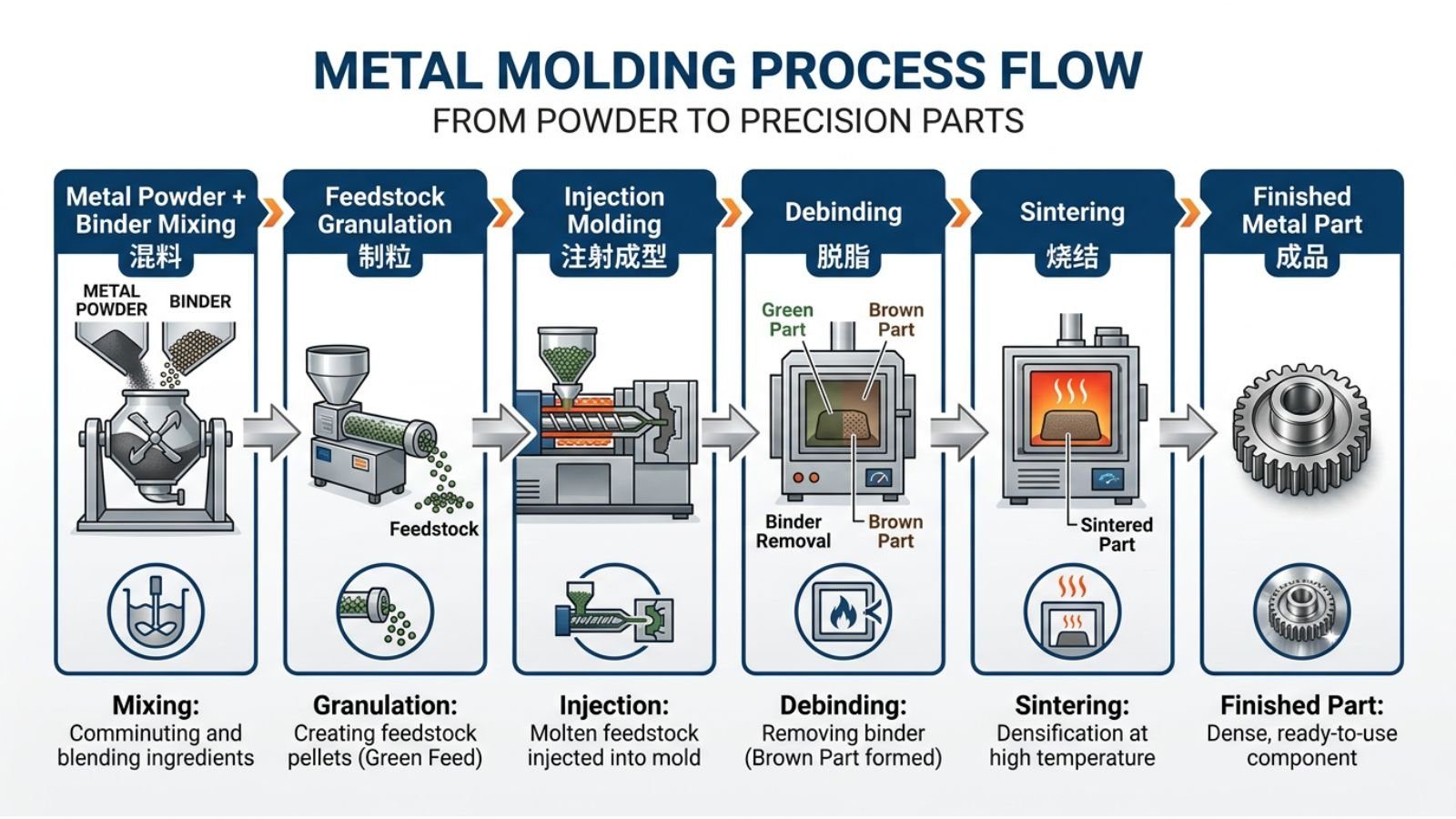
Metal Injection Molding Process in Action
Professional overview of Metal Injection Molding process from the Metal Powder Industries Federation, demonstrating feedstock preparation, injection molding, and sintering stages for precision superalloy components.
Critical Processing Parameters for IN713C
Powder Requirements: Beyond Generic Specifications
Your IN713C powder must meet requirements more stringent than stainless steels due to reactive element content.
Oxygen content specification:
- Target: <400 ppm(not <500 ppm)
- Rationale: Each 100 ppm oxygen increase correlates with 50-80 μm deeper PPB oxide penetration
- Verification: Require inert gas fusion analysis certification with every powder lot
- Compare: 316L stainless tolerates <1000 ppm with acceptable performance
Particle size distribution for IN713C:
- D90 <32 μm (not <38 μm as with some alloys)
- Rationale: Finer particles provide higher surface area for sintering, compensating for oxide films that inhibit diffusion
- Trade-off: Finer powder increases oxygen pickup risk during handling—requires inert atmosphere storage
Chemistry tolerance:
- Aluminum: ±0.3% (tighter than standard ±0.5%)
- Carbon: ±0.02% (affects grain boundary behavior)
- Rationale: Al content directly affects sintering window width; precise control essential
Sintering: Managing the Narrow Process Window
Your sintering cycle for IN713C requires parameters optimized for the specific challenges of high Al/Ti content.
Atmosphere requirements:
- High vacuum: <5×10⁻⁵ mbar (not 10⁻⁴ mbar sufficient for stainless steels)
- Rationale: Lower oxygen partial pressure marginally reduces Al₂O₃ stability
- Alternative: Ultra-pure hydrogen (dewpoint <-60°C) with oxygen getters
- Why this matters: At 10⁻⁴ mbar, Al still oxidizes; need 10⁻⁵ range
Peak temperature optimization:
- Standard range:1260°C-1270°C
- Your specific optimization: Requires thermal studies to find sweet spot within this narrow window
- Verification method: Sinter multiple batches at 5°C increments, measure density via Archimedes
- Risk: 1275°C+ approaches liquidus, causing incipient melting and distortion
Thermal profile considerations:
- Heating rate through 800-1100°C: 10-15°C/min (faster than stainless steels)
- Rationale: Minimize time at intermediate temperatures where Al oxidation kinetics are rapid but diffusion insufficient
- Hold time at peak: 2-4 hours (longer than IN718, needed for complete Al/Ti redistribution)
Debinding Strategy for Carbon Control
Your debinding approach for IN713C must balance complete binder removal with carbon content control.
The carbon management challenge:
- IN713C requires 0.08-0.20% C for grain boundary strengthening
- Binder decomposition contributes carbon
- Insufficient carbon: Reduced creep resistance
- Excess carbon: Continuous carbide networks causing brittleness
Atmosphere selection based on grade:
ForIN713C(targeting 0.12-0.14% C):
- Thermal debinding in vacuum or inert atmosphere
- Allows carbon retention from binder decomposition
- Monitor final carbon content via combustion analysis
ForIN713LC(targeting 0.03-0.05% C):
- Thermal debinding in flowing hydrogen
- Hydrogen carries away carbon as CH₄
- Requires careful temperature profiling to avoid excessive decarburization
This distinction is critical: Using the same debinding atmosphere for both grades produces different final carbon contents, affecting grain boundary behavior and post-HIP grain growth response.
Why Standard HIP Parameters Don't Apply
Generic HIP cycles (1200°C, 200 MPa) suitable for IN718 can cause problems with IN713C due to its higher Al content affecting melting behavior.
Temperature constraints for IN713C:
- Maximum: 1200°C (not 1220°C like IN718)
- Rationale: IN713C liquidus ~1260°C; safety margin of 60°C required
- Consequence of exceeding: Incipient melting of γ-γ' eutectic, surface blistering
- Compare: IN718 can safely HIP at 1220°C (liquidus ~1340°C)
Optimal HIP cycle for IN713C:
- Temperature: 1180°C (balanced for creep-based pore closure without risking melting)
- Pressure: 150-200 MPa
- Duration: 3-4 hours (longer than IN718 due to higher strength at HIP temperature)
- Cooling: Furnace cool under pressure to 600°C
Post-HIP Grain Growth for Creep Applications
If your application requires improved creep resistance, you must implement grain coarsening after HIP. This is more critical for IN713C MIM than other superalloys due to the severe creep limitation of fine-grained structure.
Grain growth treatment for IN713LC:
- Temperature: 1280°C for 8-12 hours
- Atmosphere: High vacuum or ultra-pure argon
- Expected result: Grain size increases from 25-35 μm to 50-80 μm
- Performance impact: Creep resistance improves 3-5× (still inferior to coarse cast structure)
Why IN713LC responds better than IN713C:
- Lower carbide density (0.03-0.07% C vs. 0.08-0.20% C)
- Fewer pinning particles to inhibit boundary migration
- Can achieve ASTM grain size 6-7 vs. ASTM 8-9 for IN713C
Trade-off acknowledgment:
You sacrifice some room temperature strength (5-8% decrease in YS) and fatigue life (10-15% reduction) when coarsening grains. Specify grain growth only when creep governs your design life.
Cost Analysis: When IN713C Justifies MIM Investment
Material Cost Impact: The 98% Utilization Advantage
IN713C powder is a high-value superalloy feedstock, so material waste directly impacts economics.
| Manufacturing Route | Utilization Rate | Relative Material Efficiency |
|---|---|---|
| CNC machining from billet | 30-40% | High waste |
| Investment casting | 60-70% | Moderate waste |
| MIM process | 95-98% | Low waste |
For high-volume aerospace compressor vanes, MIM's material efficiency can make it an attractive alternative to machining routes.
Break-Even Analysis: IN713C Specific Factors
Tooling cost for IN713C components is typically higher than for stainless steels due to:
- More aggressive wear on mold surfaces (harder powder)
- Tighter dimensional tolerances required (narrow shrinkage window)
- More complex mold cooling design (thermal sensitivity)
Typical tooling investment:
- Tooling for IN713C aerospace or turbocharger components is typically higher than for stainless steel due to harder powder, tighter tolerances, and thermal sensitivity.
Break-even volume (vs. investment casting):
- Simple geometry: typically tens of thousands of units/year
- Complex geometry: often thousands to tens of thousands of units/year
The crossover point occurs at lower volumes than stainless steel MIM because IN713C's material cost is higher, making waste reduction more valuable.
Cost Comparison: Aerospace Compressor Vane
Qualitative comparison for a typical IN713C compressor vane
MIM + HIP can offer lower material waste and reduced machining for complex vanes, but actual savings depend on part geometry, annual volume, and supplier process. Buyers should request a detailed quote comparing MIM + HIP against investment casting + machining for their specific design.
Material Specification for Procurement
When you write procurement specifications for IN713C MIM components, include these parameters:
Powder specification:
Base Material: IN713C per AMS 5391 (or IN713LC variant)Production Method: Argon gas atomizationParticle Size: D10 ≥8 μm, D50 15-25 μm, D90 ≤32 μmOxygen Content: ≤400 ppm (certified analysis required each lot)Chemistry Tolerances: - Aluminum: 5.8-6.3% (±0.3%) - Carbon: ±0.02% of specification - All other elements: ±0.5% of nominal
Sintering requirements:
Atmosphere: Vacuum ≤5×10⁻⁵ mbar or H₂ (dewpoint ≤-60°C)Peak Temperature: 1260-1270°C (specify after process optimization)Temperature Uniformity: ±3°C across working zoneHold Time: 3-4 hours minimumMinimum As-Sintered Density: 98.0% theoretical
HIP specification:
Mandatory for all fatigue-critical applicationsCycle: 1180°C, 180 MPa, 3 hours minimumPost-HIP Density: ≥99.5% theoretical (Archimedes verification)Porosity Limits: No pores >50 μm, total porosity <0.3% by volume
Mechanical properties (room temperature minimums):
0.2% Yield Strength: 700 MPaUltimate Tensile Strength: 950 MPaElongation: 6% minimumReduction of Area: 8% minimumFor 650°C properties:0.2% Yield Strength: 750 MPaUltimate Tensile Strength: 1000 MPa
IN713C-Specific Supplier Qualification
Beyond general MIM capability, verify these IN713C-specific competencies:
Material experience:
- ☐ Documented production history with IN713C or IN713LC (not just IN718)
- ☐ Understanding of Al/Ti oxide formation challenges
- ☐ Reference accounts for high-γ' nickel superalloys
- ☐ Metallurgical staff with superalloy expertise
Process capability:
- ☐ Powder oxygen control <400 ppm (provide data from recent lots)
- ☐ Vacuum sintering capability <5×10⁻⁵ mbar (provide vacuum logs)
- ☐ Temperature uniformity ±3°C demonstrated via thermal survey
- ☐ Documented process window for IN713C (temperature-density curve)
Quality systems for reactive alloys:
- ☐ Inert atmosphere powder storage and handling
- ☐ Powder oxygen testing protocol for incoming material
- ☐ Atmosphere monitoring during debinding and sintering
- ☐ CT scanning capability to 50 μm resolution
HIP specification for IN713C:
- ☐ HIP temperature limited to ≤1200°C (not standard 1220°C cycle)
- ☐ Documented cycle appropriate for high-Al superalloys
- ☐ Pre- and post-HIP density verification procedures
Real-World Applications: Validated IN713C MIM
Aerospace: IN713C Stator Vanes
IN713LC MIM stator vanes have been evaluated for safety-critical aerospace hardware, demonstrating the technology's potential readiness when the process is qualified.
Application requirements:
- Operating temperature: up to ~850°C (hot section gas path)
- Primary loading: High-cycle fatigue from blade passing vibrations
- Design life: many thousands of flight hours
- Annual production: high-volume runs
Why MIM can be selected:
- Complex airfoil geometry with internal cooling passages
- Thin trailing edges difficult to cast consistently
- High-volume production suited to automated MIM
- Potential for fatigue life comparable to or better than cast baseline
Typical process specifications:
- IN713LC powder with low oxygen content
- Vacuum sintering in the 1260–1270°C range
- Mandatory HIP at ~1180°C, ~150–200 MPa
- CT scanning for internal porosity verification
Successful field experience would validate the technology for this application class; specific flight-hour claims require verification from the qualifying party.
Automotive: Gasoline Turbocharger Wheels
IN713C turbine wheels for gasoline engine turbochargers represent high-volume MIM success in extremely demanding thermal cycling environment.
Application requirements:
- Exhaust gas temperature: 950-1050°C peak
- Rotational speed: >120,000 RPM (high centrifugal stress)
- Thermal cycling: Startup/shutdown fatigue dominates life
- Annual volume: high-volume runs (automotive scale)
Why IN713C rather than lower-cost alternatives:
- Superior oxidation resistance (high Cr, Al) vs. IN718 above 850°C
- Better thermal stability than stainless steels or tool steels
- Cost justified by performance in severe environment
MIM advantages over investment casting:
- Complex blade array geometry reproduced to near-net-shape
- No machining of fragile blade airfoils required
- Microstructural uniformity improves dynamic balance
- Superior thermal fatigue resistance (fine-grained structure advantageous)
Process adaptations for this application:
- Shrinkage uniformity critical for dynamic balance (±0.05% tolerance)
- Post-HIP machining of hub and bore only
- 100% automated dynamic balancing verification
Common IN713C-Specific Failure Modes
Prior Particle Boundary (PPB) Oxide Failures
This is the signature failure mode of improperly processed IN713C MIM components, directly related to the Al₂O₃ formation problem.
Identification:
- Intergranular fracture along boundaries not corresponding to grain boundaries
- Fracture surface shows spherical particle outlines under SEM
- EDS analysis confirms oxygen-rich (10-20 at% O) regions at boundaries
- Cross-section metallography reveals incomplete particle bonding
Root cause analysis:
- Powder oxygen content >500 ppm
- Insufficient vacuum during sintering (>10⁻⁴ mbar)
- Heating rate too slow through 800-1100°C (prolonged oxidation time)
- Combination of above factors
Why this differs from other alloys:
- Stainless steel MIM tolerates higher oxygen (forms reducible FeO, Cr₂O₃)
- IN718 with lower Al content shows less severe PPB oxidation
- IN713C's 6% Al makes PPB oxides virtually unavoidable without extreme control
Corrective actions:
- Reject powder lots >400 ppmoxygen
- Upgrade vacuum system to <5×10⁻⁵ mbar capability
- Increase heating rate to 10-15°C/min through critical range
- Consider hydrogen sintering atmosphere (reduces oxides better than vacuum)
Insufficient Density Post-Sintering
Achieving >98% density in as-sintered condition is critical for effective HIP—yet IN713C's narrow sintering window makes this challenging.
Symptoms:
- As-sintered density 95-97% (below 98% target)
- HIP cannot fully close interconnected porosity
- Final properties show high variability batch-to-batch
IN713C-specific causes:
- Sintering temperature 10-15°C below optimum (conservative setting to avoid incipient melting)
- Poor temperature uniformity causes parts at furnace periphery to under-sinter
- Powder particle size D90 >35 μm (sintering kinetics too slow)
Diagnostic approach:
- Map density vs. furnace position to identify thermal gradients
- Sinter test coupons at 5°C increments to find true process window
- Verify powder particle size distribution meets D90 <32 μm
Solutions:
- Thermal survey of furnace to verify ±3°C uniformity
- Optimize loading pattern to avoid cool zones
- If furnace limitation exists, consider shorter sintering time at +10°C higher temperature
- Specify finer powder fraction for improved sinterability
Frequently Asked Questions
Q: Why does IN713C have a narrower sintering window than IN718?
IN713C contains ~8 wt% combined Al+Ti (for high γ' volume fraction) vs. ~5.5 wt% in IN718. This higher γ'-forming element content affects the solidus and liquidus temperatures, creating a steeper temperature-density relationship. The consequence: 20°C window for IN713C vs. 50°C for IN718. Your process control requirements are accordingly more stringent.
Q: How does carbon content choice affect your post-processing options?
If you plan post-HIP grain growth treatment to improve creep resistance, specify IN713LC (0.03-0.07% C). The lower grain boundary carbide density allows boundaries to migrate during high-temperature annealing. IN713C (0.08-0.20% C) resists grain growth due to carbide pinning. This choice must align with your application: fatigue-limited (either grade) vs. requiring creep enhancement (specify IN713LC).
Q: Why is oxygen control more critical for IN713C than stainless steels?
Aluminum and titanium form more stable oxides (Al₂O₃ ΔG = -1100 kJ/mol at 1260°C) than iron or chromium oxides (FeO ΔG = -240 kJ/mol). These Al₂O₃ films persist through sintering, decorating prior particle boundaries and preventing metallurgical bonding. Stainless steels with <1000 ppm oxygen perform acceptably because FeO and Cr₂O₃ partially reduce in vacuum. IN713C requires <400 ppmbecause Al₂O₃ won't reduce under practical sintering conditions.
Q: Can IN713C MIM achieve the same creep resistance as cast material?
Not with standard processing. As-sintered + HIP produces fine grains (25-35 μm) with poor creep resistance due to extensive grain boundaries facilitating diffusion creep. Post-HIP grain growth treatment (1280°C, 8-12 hours) can coarsen grains to 50-80 μm, improving creep 3-5×—but still inferior to coarse cast grains (>500 μm). If long-term creep at >850°C governs your design, investment casting remains superior. Select MIM when fatigue, not creep, limits component life.
Q: What distinguishes IN713C from IN718 for MIM processing?
IN713C's higher aluminum content (6% vs. 0.5%) creates greater oxide formation challenges and narrower sintering window, making processing more difficult. However, you gain superior oxidation resistance and higher service temperature capability (950°C vs. 650°C for IN718). Choose IN713C when you need oxidation resistance >850°C (turbocharger wheels, hot section vanes). Choose IN718 for <750°C applications where easier processing and lower powder cost matter more.
Q: Why specify 1180°C for HIP instead of the standard 1200°C cycle?
IN713C liquidus temperature (~1260°C) is lower than IN718 (~1340°C) due to higher Al content affecting melting behavior. Standard 1200°C HIP (used for IN718) provides only 60°C margin from liquidus for IN713C—too small for safety. The 1180°C specification provides 80°C margin, preventing any risk of incipient melting during HIP while still achieving effective pore closure through creep-based densification.
Q: How do you prevent Al₂O₃ formation at prior particle boundaries?
Implement four-layer defense: (1) Source powder with <400 ppmoxygen via certified argon atomization; (2) Store and handle powder in inert atmosphere glove boxes; (3) Sinter in high vacuum <5×10⁻⁵ mbar or ultra-pure hydrogen; (4) Use rapid heating (10-15°C/min) through 800-1100°C to minimize time at temperatures where oxidation kinetics are rapid but diffusion insufficient. All four layers required—single failure point causes PPB oxides.
Q: Why choose IN713C over IN718 for turbocharger wheels?
Above 850°C, IN718 oxidizes rapidly (forms non-protective scale) while IN713C maintains excellent oxidation resistance due to higher chromium (13% vs. 18%) and aluminum content forming protective Cr₂O₃/Al₂O₃ scales. For gasoline turbochargers with 950-1050°C exhaust gas, IN713C justifies its higher powder cost through extended component life. Diesel turbochargers operating <750°C use IN718 for better economics.
Q: What causes density variation within a single batch of parts?
IN713C's narrow sintering window (20°C) makes density extremely sensitive to temperature variations. Furnace thermal gradients of ±5°C—acceptable for stainless steels—cause 1.5-2% density variation in IN713C parts. Parts at furnace periphery or near heating elements experience different thermal histories. Solution: Conduct thermal survey to verify ±3°C uniformity, optimize loading pattern to avoid hot/cold spots, consider smaller batch sizes for critical applications.
Q: How do you verify that HIP successfully closed all porosity?
Three-method verification: (1) Archimedes density measurement should show >99.5% theoretical (vs. 98% pre-HIP); (2) Industrial CT scanning at 50 μm resolution visualizes remaining pores—specify zero pores >50 μm diameter; (3) Metallographic cross-sections at 500× magnification confirm absence of spherical voids. For aerospace applications, require 100% CT scanning with documented porosity analysis. Batch sampling insufficient due to high consequence of failure.
Conclusion: Strategic Deployment of IN713C MIM
Metal Injection Molding for IN713C represents a qualified manufacturing technology for specific high-performance applications where the inherent performance trade-off aligns with design requirements.
You must base your adoption decision on rigorous analysis of three factors:
Performance alignment:Your component's dominant failure mode must be fatigue rather than creep, with service temperature predominantly below 850°C. The fine-grained MIM structure excels in fatigue resistance but cannot match coarse-grained castings for creep. This fundamental trade-off is non-negotiable.
Economic justification:The technology becomes compelling when high IN713C powder cost combines with complex geometry that makes conventional machining wasteful. At production volumes exceeding thousands of units annually, MIM's high material efficiency and near-net-shape capability can deliver meaningful cost reduction versus traditional routes.
Processing capability:IN713C's narrow sintering window, high oxygen reactivity, and specific HIP requirements demand supplier capabilities beyond generic MIM competency. Your supplier must demonstrate specific experience with high-aluminum nickel superalloys, not just ferrous materials or lower-reactivity alloys.
The mandatory specification of Hot Isostatic Pressing for any safety-critical application cannot be overemphasized. HIP at 1180°C (not the 1200°C cycle used for IN718) eliminates residual microporosity that would otherwise serve as fatigue crack initiation sites, transforming MIM from near-net-shape to high-integrity manufacturing.
For aerospace compressor vanes and automotive turbocharger wheels operating in fatigue-limited, thermally cyclic environments below 850°C—with production volumes justifying tooling investment—IN713C MIM can deliver strong performance and economic benefits when the process is properly qualified.
The future expansion of IN713C MIM into creep-limited applications depends on continued refinement of post-HIP grain growth treatments. Current capabilities using IN713LC with controlled grain coarsening show promise but cannot yet match coarse-grained casting performance. This remains the primary technical barrier to broader adoption.
Your specification and procurement strategy must reflect IN713C's unique processing challenges: oxygen control <400 ppm, vacuum sintering <5×10⁻⁵ mbar, and HIP parameters appropriate for high-aluminum superalloys. Suppliers meeting these requirements transform MIM into a capable manufacturing route for this demanding material.
About This Analysis
This technical analysis integrates data from aerospace evaluations of IN713LC MIM stator vanes, automotive turbocharger wheel applications, controlled research studies on IN713C powder metallurgy, and established MIM processing parameters. Performance data and process specifications reflect commonly reported industry values and laboratory studies; project-specific results should be verified with your supplier.
Custom MIM Parts from Emitech
Nanjing Emitech delivers MIM 316L, 17-4PH, 4340 and other materials from tooling through sintering and finishing. Custom MIM parts · MIM services · Request a quote
Last updated: 2026-06-24
Continue reading
- MIM vs MBJ: Which Metal Manufacturing Technology Is Right For Your Project?
- Metal Injection Molding (MIM) vs. Powder Metallurgy (PM)—Which Is Best for You?
- MIM vs Sintering: Understanding the Difference (One Is Part of the Other)
- MIM's External and Internal Undercut Design: Complex, Cheap, and Fixing Production Issues