
You've invested in precision MIM components, but now you need to join them. The question keeps coming up: will welding destroy the sintered structure? Here's the truth: MIM parts weld successfully when you understand their unique metallurgy—and manufacturers worldwide prove it daily with high success rates.
Complete overview of Metal Injection Molding technology merging plastic injection molding and powdered metallurgy to produce complex metal components with exceptional design freedom
Understanding What You're Working With: The MIM Microstructure
Before you strike an arc or fire up a laser, you need to understand that your MIM components aren't just "regular metal parts." These components underwent a complex journey from powder to solid, and that journey leaves behind a specific microstructural fingerprint that directly impacts how they'll behave under welding heat.
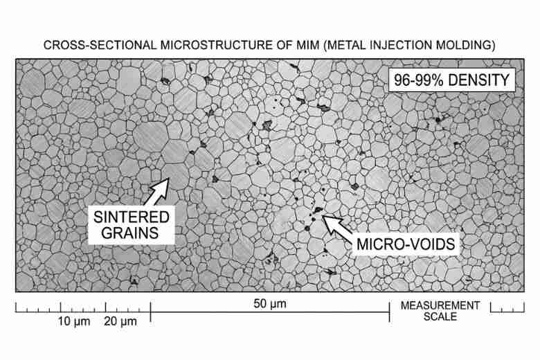
MIM components contain 96-99% density with 1-4% microscopic voids—understanding this structure is critical for successful welding
Your MIM parts contain 96-99% density after sintering, meaning 1-4% of the volume exists as microscopic voids. These aren't defects—they're an inherent characteristic of the powder metallurgy process. During welding, gases trapped in these voids expand rapidly according to the ideal gas law (PV=nRT), potentially causing weld porosity if you don't manage heat input carefully.
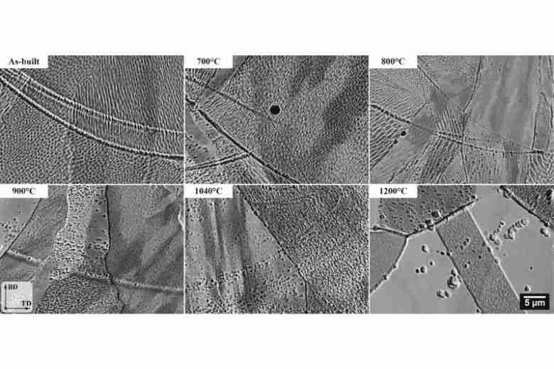
Quantitative analysis demonstrating the direct relationship between residual porosity levels, microstructure characteristics, and resulting mechanical properties in MIM materials
The fine, equiaxed grain structure you're working with—typically 10-50 micrometers—differs fundamentally from the elongated grains in wrought materials. This uniform structure actually provides certain advantages: reduced hot cracking susceptibility and more predictable heat distribution. However, it lacks the beneficial grain flow of forged components, impacting fatigue performance in welded assemblies.
Yes, You Can Weld MIM Parts—Here's How
The Definitive Answer
Your MIM components possess the same chemical composition and crystal structure as their wrought counterparts. The metallurgical bonds formed during sintering are fundamentally similar to grain boundaries in conventional metals. This means standard welding processes work—but require specific parameter adjustments.
Yes, MIM products can be welded! This demonstration shows the high metal powder content in MIM components enables successful welding when proper techniques are applied
Industry data confirms this: aerospace manufacturers routinely laser weld titanium MIM components, medical device companies join 316L surgical instruments, and automotive suppliers weld millions of 17-4 PH assemblies annually. Success depends on process selection and parameter control.
Your Welding Process Options, Ranked
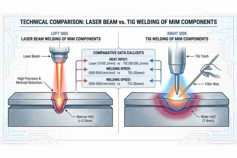
Laser welding offers superior precision with minimal heat input (10-50 J/mm) compared to TIG welding, making it ideal for high-volume MIM component assembly
1. Laser Beam Welding (Your Best Option for Automation)
- Heat input: 10-50 J/mm (compared to 100-500 J/mm for TIG)
- HAZ width: <0.5mm typical
- Welding speed: 500-5000 mm/min
- Ideal for: High-volume production, components <3mm thickness
For your 17-4 PH components, use pulsed Nd:YAG lasers at 15-20 J/mm³ energy density. You'll achieve full penetration on 0.7mm sections with continuous wave CO₂ lasers at 1500-1600W and 700 mm/min travel speed.
Advanced laser welding technique joining 420 stainless steel onto beryllium copper injection molding cores—demonstrating precision welding capabilities for complex MIM tooling applications
2. TIG Welding (Your Most Versatile Option)
- Heat input: 50-200 J/mm
- HAZ width: 1-3mm typical
- Operator skill required: High
- Ideal for: Low-volume, repair work, dissimilar thickness joints
When TIG welding your 316L components, start with these parameters:
- 1.6mm thickness: 50-80A DCEN
- 2.4mm thickness: 120-175A DCEN
- Shielding gas: Pure argon at 20-25 CFH
- Filler: ER316L, matching chemistry critical for corrosion resistance
3. Resistance Welding (For Specific Geometries)
- Heat input: Highly localized
- Cycle time: <1 second
- Ideal for: Overlapping joints, high-volume spot welding
Critical Challenges You Must Address
The Porosity Problem
Your primary challenge stems from those 1-4% voids. When you apply welding heat, trapped gases expand, creating two failure modes:
- Immediate porosity: Gas escapes into your weld pool, forming spherical voids that reduce cross-sectional strength by up to 30%
- Delayed cracking: Expanded gas trapped during rapid cooling creates internal pressure, initiating micro-cracks hours after welding
Your solution: Minimize heat input and use pulsed processes. Each pulse allows partial solidification and gas escape. For critical applications, specify vacuum-sintered MIM parts to eliminate atmospheric gases in pores.
Residual Binder Contamination
Even with 98%+ binder removal, trace organics can remain. At welding temperatures, these decompose into hydrogen and carbon-containing gases. In your austenitic stainless steels, this causes chromium carbide precipitation at grain boundaries—the dreaded sensitization that destroys corrosion resistance.
Your solution: Request certificates showing <0.02% residual carbon from your MIM supplier. For existing inventory, perform vacuum bakeout at 400°C for 2 hours before welding.
Material-Specific Considerations
For Your 17-4 PH Parts:
 Micrographs of MIM 17-4PH Stainless Steel Sintered at 1330°C in Conventional Vacuum Furnace
Actual metallographic images of MIM 17-4PH stainless steel sintered at 1330°C, revealing the grain structure and residual porosity typical of metal injection molded components
- No preheating required (simplifies your process)
- Use ER630 filler wire exclusively
- Critical: You MUST perform post-weld aging. The weld heat solution-anneals your HAZ, dropping hardness to ~30 HRC. Without aging at 482°C (H900) or 621°C (H1150), you're leaving significant potential strength on the table.
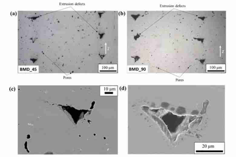
Comprehensive defect analysis of MIM 17-4PH components identifying common defect types, pore characteristics, and their impact on weldability and joint quality
For Your 316L Parts:
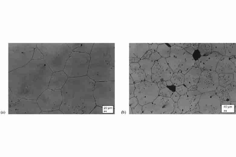
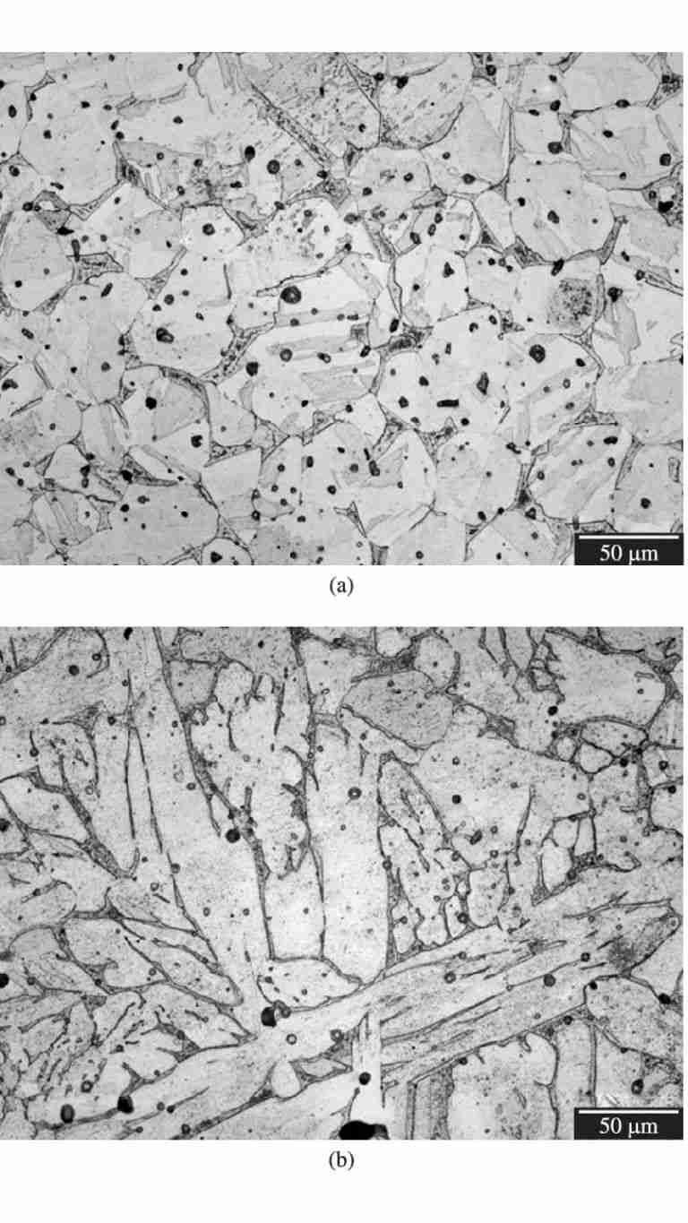
MIM 316L stainless steel microstructure comparison: (a) as-sintered condition at 1350°C and (b) after corrosion testing, demonstrating the material's structural integrity
- Maximum interpass temperature: 150°C (prevents sensitization)
- Never use stress relief unless absolutely necessary—holding at 425-815°C actually causes the carbide precipitation you're trying to avoid
- In as-welded condition, you'll maintain full corrosion resistance
Your Pre-Welding Checklist
Before you weld, complete these non-negotiable steps:
- Mechanical cleaning: Stainless steel wire brush (never use carbon steel tools)
- Degreasing: Acetone wipe extending 25mm beyond joint
- Surface inspection: Check for visible porosity or cracks at 10X magnification
- Fixture verification: Copper backing bars positioned for heat extraction
- Shield gas purge: 60 seconds pre-flow to displace atmospheric gases
Skip any step, and you're gambling with joint integrity.
Post-Weld Requirements That Make or Break Your Joint
For 17-4 PH: Mandatory Aging Cycles
Your welded assembly isn't complete until aged. Choose based on application:
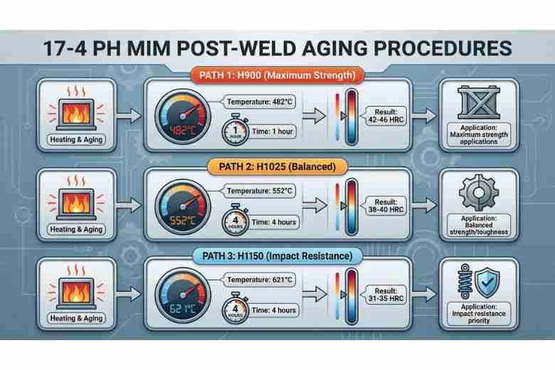
Post-weld aging is mandatory for 17-4 PH MIM assemblies—choose H900, H1025, or H1150 condition based on your strength and toughness requirements
| Condition | Temperature | Time | Resulting Hardness | Use Case |
|---|---|---|---|---|
| H900 | 482°C | 1 hour | 42-46 HRC | Maximum strength applications |
| H1025 | 552°C | 4 hours | 38-40 HRC | Balanced strength/toughness |
| H1150 | 621°C | 4 hours | 31-35 HRC | Impact resistance priority |
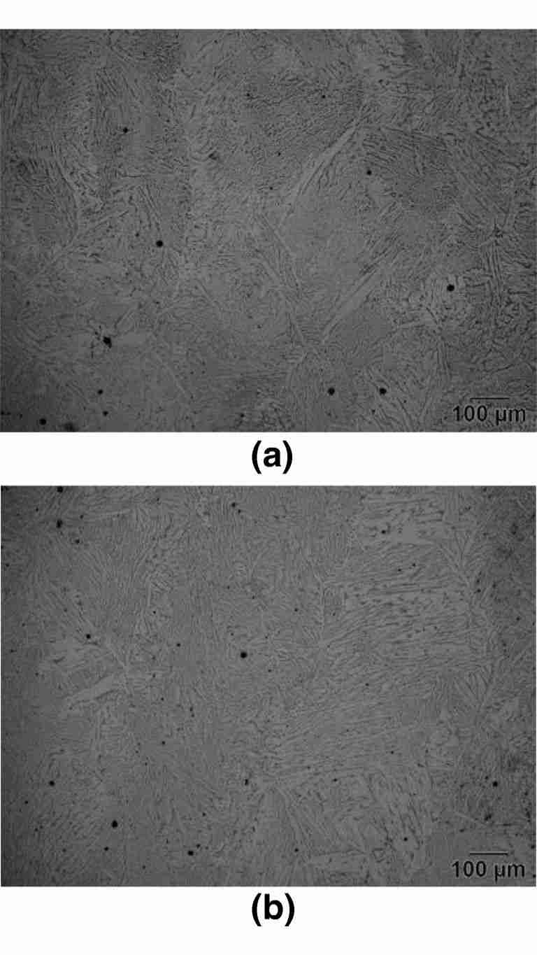
Microstructural transformation in 17-4 PH stainless steel: (a) solution-treated condition before aging and (b) after aging heat treatment, showing precipitate formation that increases hardness and strength
For 316L: Minimal Intervention
Your best post-weld treatment for 316L? Nothing. The austenitic structure is stable. Any heat treatment between 425-815°C risks sensitization. If distortion is unacceptable, use mechanical straightening rather than thermal stress relief.
Real Performance Data You Need
Static Strength
Your properly welded MIM joints achieve:
- most of base material UTS
- most of base material yield strength
- Elongation close to that of parent material
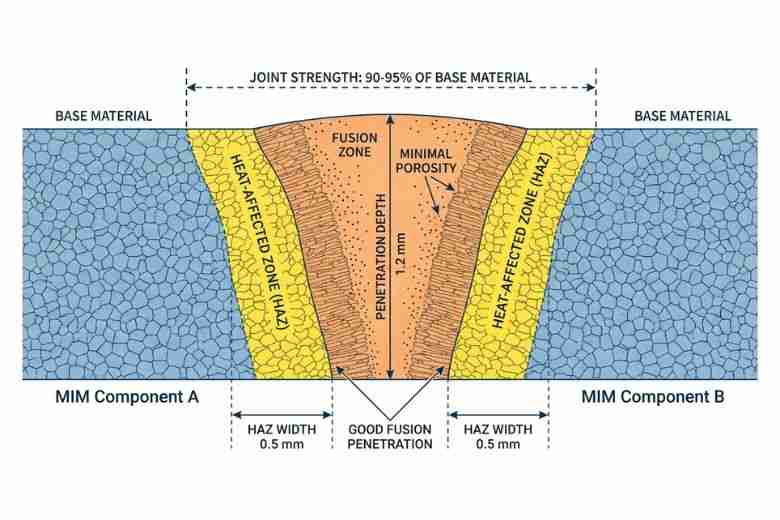
Properly welded MIM joints achieve 90-95% of base material strength with controlled heat-affected zones and minimal porosity
Fatigue Performance (The Critical Limitation)
Here's what manufacturers don't always tell you: welded MIM components show lower fatigue life than welded wrought equivalents. The combination of residual porosity and lack of grain flow creates multiple crack initiation sites.
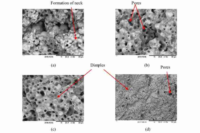
Fracture surface analysis of MIM components: (a) 1,100°C 3h, (b) 1,200°C 3h, (c) 1,300°C 3h, and (d) SLM comparison, revealing the impact of sintering temperature on material density and fracture behavior
Your design solution: Apply a 1.5X safety factor for cyclic loading applications compared to wrought materials. For infinite life designs, limit stress to 40% of ultimate tensile strength rather than the typical 50% for wrought materials.
Quality Validation You Can't Skip
Non-Destructive Testing Requirements
- Visual inspection: 100% at 10X magnification
- Dye penetrant: For surface-breaking defects (especially in HAZ)
- X-ray: For porosity quantification in critical joints
- Ultrasonic: For full-penetration verification on sections >3mm
Destructive Testing for Procedure Qualification
Before production, validate your procedure with:
- Cross-section metallography (verify fusion, check porosity)
- Tensile testing (confirm 90% minimum strength retention)
- Fatigue testing (10^6 cycles at expected service loads)
When NOT to Weld Your MIM Parts
Consider alternatives when:
- Annual volume <10,000 units (tooling for single-part MIM may be economical)
- Wall thickness <0.5mm (distortion risk exceeds benefit)
- Fatigue safety factor <3X available (use mechanical fastening or adhesive bonding)
- Joining to plastics or ceramics (brazing or adhesive bonding required)
Emerging Technologies for Your Future Applications
Friction Stir Welding (2-3 Years Out)Research shows 40% reduction in porosity-related defects compared to fusion welding. Currently limited to flat geometries but expanding rapidly.
AI-Optimized Parameters (Available Now)Cloud-based services offer real-time parameter optimization based on your specific alloy and thickness. ROI typically achieved within 5000 parts for high-mix production.
Laser welding for molds demonstrates the ideal solution for repairing cracks, pinholes, edge wear, and surface defects without damaging the base material—techniques directly applicable to MIM component repair
Nano-Powder MIM Materials (Now Entering Market)New <5 micron powder materials achieve 99.5% density, effectively eliminating porosity concerns. Premium cost (30-40% higher) justified for aerospace and medical applications.
Frequently Asked Questions
Q: Do I need special welding equipment for MIM parts?
No. Your existing TIG, MIG, or laser equipment works perfectly. You're adjusting parameters, not replacing hardware. Reduce heat input by 15-20% from your wrought material settings as a starting point.
Q: Can I weld MIM to wrought materials?
Yes, this is routine. The fusion zone doesn't "know" the difference. Match your filler to the weaker material's chemistry and use parameters based on the MIM component's requirements.
Q: What's the minimum MIM density for reliable welding?
You need 96% minimum, but 98%+ dramatically improves success rates. Below 96%, excessive porosity makes consistent welding nearly impossible.
Q: How do I handle distortion in thin-walled MIM assemblies?
Pre-bend components opposite to expected distortion (typically 0.5° per 10mm of weld). Use stepped welding sequences and intermediate stress relief via vibratory methods rather than thermal treatment.
Q: Why did my 17-4 PH weld crack after 24 hours?
Delayed hydrogen cracking from inadequate post-weld aging. The un-aged martensite is highly susceptible to hydrogen embrittlement. Perform H900 aging within 4 hours of welding to prevent this.
Q: Can I repair a failed MIM weld?
Yes, but only once. Each thermal cycle increases grain size and porosity coalescence. Second repairs show 60% lower success rates. Design for replacement rather than multiple repairs.
Your Action Plan
Successfully welding MIM parts requires respecting their powder metallurgy origins while leveraging their near-wrought properties. Start with high-density materials (>98%), choose low heat input processes (laser or TIG), and never skip post-weld treatments for precipitation-hardening alloys.
Remember: you're not just joining metal—you're managing a complex microstructure with a unique thermal history. Respect that complexity with proper procedures, and you'll achieve the 95%+ success rates that make MIM welding a viable production process. Our MIM production capabilities page documents the sintering density controls and inspection steps behind that reliability.
The investment in understanding these nuances pays dividends: reduced scrap rates, predictable quality, and the ability to create complex assemblies that leverage MIM's geometric freedom with welding's joining flexibility.
Need specific welding procedures for your MIM application? Our metallurgical engineering team provides customized WPS development and validation services for critical components.
Precision Metal Parts from Emitech
Nanjing Emitech delivers MIM, CNC machining, and custom metal parts. MIM services · Request a quote
Last updated: 2026-06-24
Continue reading
- MIM vs Sintering: Understanding the Difference (One Is Part of the Other)
- MIM's External and Internal Undercut Design: Complex, Cheap, and Fixing Production Issues
- Oil Impregnated Bronze Bushings: The Complete Guide for Engineers and Buyers
- How P.A.N.A.C.E.A. Stainless Steel Performs in MIM Sintering: An In-Depth Technical Analysis